Through some further experimenting, the design of the REPLY indicator was changed a little bit. It now uses two .125″ diffuser layers and a single .062″ Rowmark lettering layer. This results in a MUCH better visual result, with no hot spots or faded areas in the indicator.

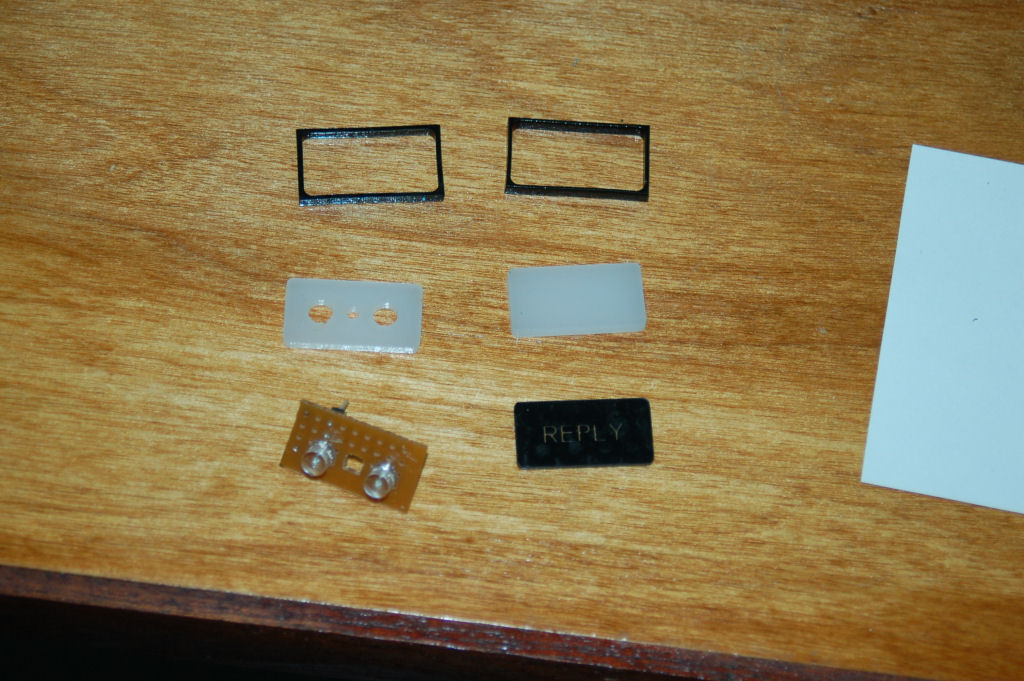
The parts that make up the REPLY indicator
Only the back diffusion layer has holes cut out for the LEDs. The LEDs themselves are shaped like flat top cylinders instead of the rounded top you normally see with LEDs. The two small black frames were made to more closely emulate the look of the original indicator.

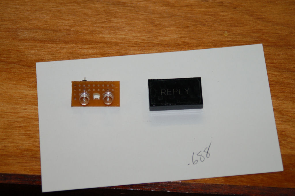
The assembled REPLY indicator next to the LED circuit board.
The two LEDs used are 3.0v 180 degree FOV green LEDs. These LEDs can be purchased from here: http://myworld.ebay.com/cece718.
Here’s a short video that shows the indicator in action. Note that the camera I use was pretty much overwhelmed by the light from the LEDs. It’s really not that bright in person.
httpv://www.youtube.com/watch?v=BK9-v67XUFw
Comments
Leave a Reply


Valisk_61 on 09.14.2009
Shame your supplier doesn’t ship to the UK… He has everything!