

The flight control system on the F-15 is a cross between a fly-by-wire system and a standard hydro-mechanical system. The F-15 has a system called the CAS, or Control Augmentation System that combines the best features of the old and new styles of flight controls.
In order to accomplish this, McDonnell-Douglas needed a way to detect the amount and direction of force the pilot was applying to the flight grip. This is how the SFS or Stick Force Sensor box was born. This box not only joins the grip to the stick base, but also contains a “load beam”. This is a special electronic device that tells the flight control computer how much force the pilot is applying to the stick and in what direction. The SFS box also contains the Autopilot Disconnect and Nosewheel Steering paddle.
Here’s what the components of my implementation look like:
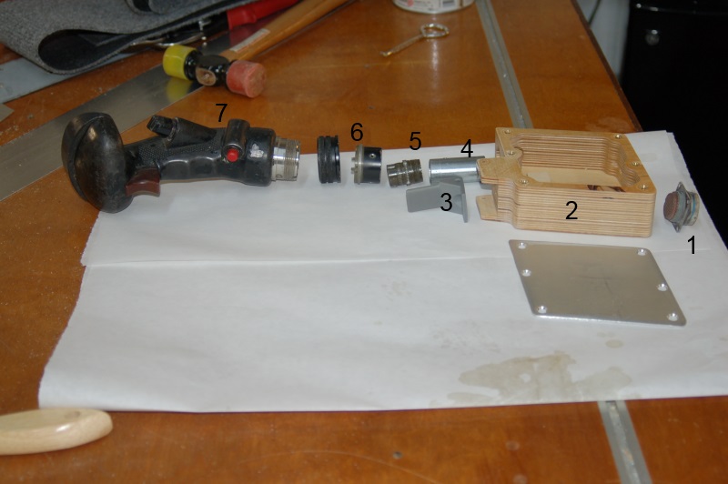
SFS Box Parts
- 57 pin cannon socket
- CNC machined Baltic Birch SFS box and aluminum cover
- AP/NWS paddle (3D printed)
- Replica Load Beam
- 57 pin cannon socket
- Grip support and threaded locking ring
- F-15C, Post-MSIP II Flight Grip (made of pure unobtanium!)
Part #1 – the 57 pin cannon plug was part of the original wiring harness for the SFS box. However, instead of being mounted to the box, this connector was attached to the cockpit floor with four screws. The other end of the cable (not shown) was a 57 pin cannon plug that mated to the SFS box itself. I’m going to rebuild the harness using a different connector to pass the wiring through the cockpit floor and use the original parts to build a visually correct SFS box.
Part #2 – the machined SFS box was covered here a number of years ago. Other projects and an ugly case of Stage IIIB lung cancer put the whole thing on hold for a long time.
Part #3 is a pretty good replica of the original AP/NWS paddle. I printed it on my Rostock MAX 3D printer.
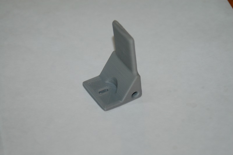
AP/NWS Paddle
The part is 30mm tall and 30mm wide at the base. It’s not an exact copy of the paddle, but it’s pretty close!
Part #4 – the “load beam” is simply a short piece of 3/4″ EMT that’s been turned on a lathe to increase the inside diameter a bit in order that the 57 pin cannon plug (Part 5) can fit inside.
Part #5 – the 57 pin cannon plug mates to the keyed socket on the flight grip.
Part #6 – the lower ring is custom fabricated by a friend of mine and the threaded ring was a donor part from another aircraft. Fortunately the USAF loves their standards, so most of the parts at that level are the same with respect to thread diameter and pitch.
I’ve got the pinout for the grip and I just need to verify it with a meter. Once I’m confident that I have a 100% good pinout and all the switches work, I’ll build the harness that joins the two cannon connectors together and then permanently mount the connector to the bottom of the SFS box.
Not shown is a Delrin post that bolts to the bottom of the SFS box – this is what mates the SFS box to the lower stick mechanism in the cockpit.
This past week I got the “beam” glued into the SFS box using JB Weld:
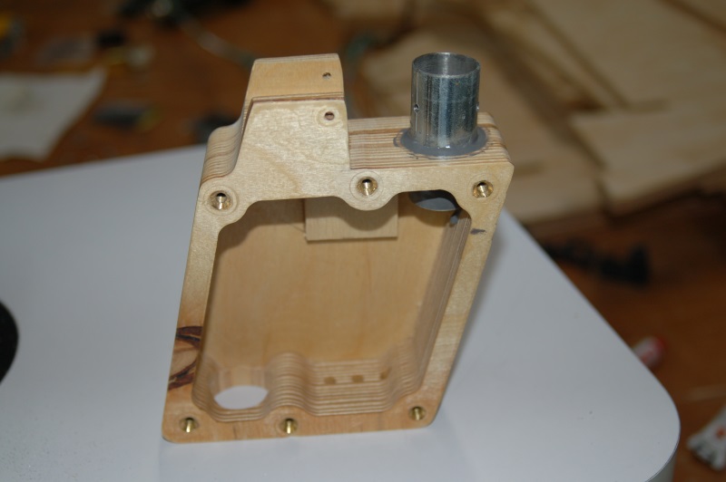
“Beam” mounted to the SFS box.
I’m going to add a smaller support piece in there to help protect the tube against aggressive back-force. It’s well supported to the rear, but not to the front.
The little square of material you can see is where the micro-switch for the AP/NWS paddle goes.
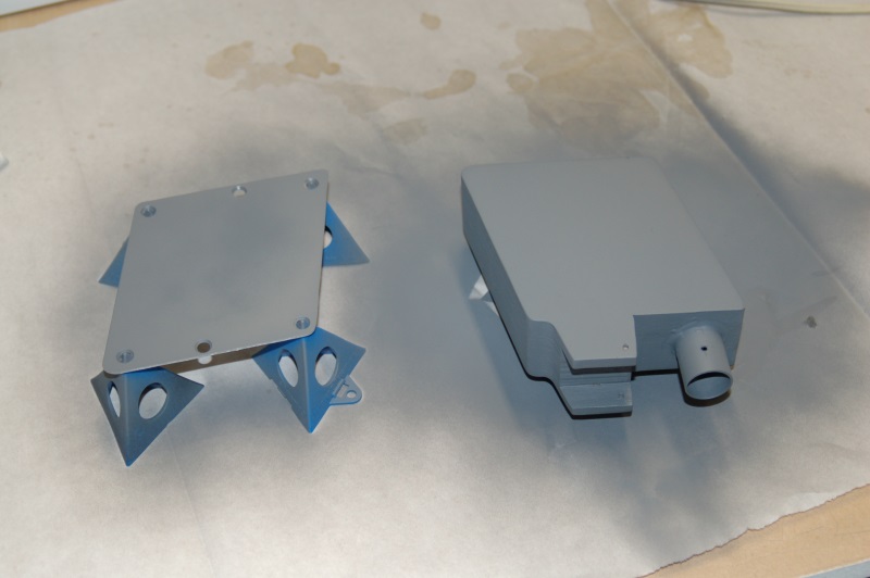
SFS painted with a first coat of primer.
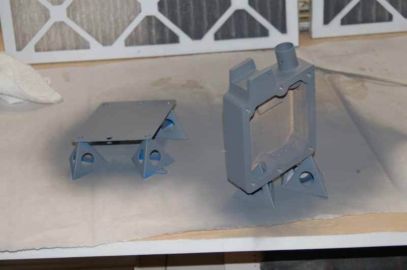
Another angle…
I used a Krylon flat primer and before I install it into the cockpit, I’ll shoot it again with the correct FS color that it should be. The grey primer isn’t light enough.
A number of years ago, I scored a pile of the Bay 5 relay boxes on eBay. I got tired of moving them around the shop this week, so I installed them. 🙂 Each one is in the correct location according to the matching placards on each one. 🙂
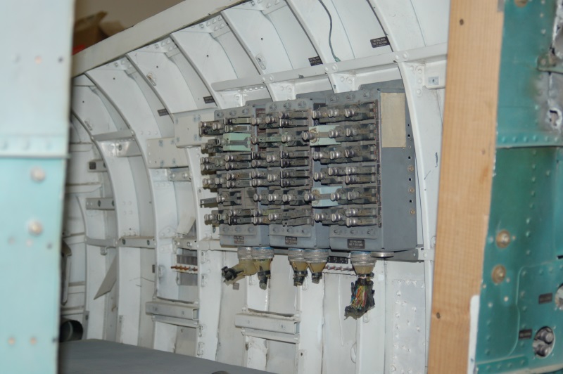
More next week!
Comments
Leave a Reply


DAD on 03.23.2013
Glad you are enjoying your hobby. It gets better and better…love Dad B-}
John on 07.01.2018
What is the part number of the amp connector mounted on the sensor box that interfaces with the stick grip? I have an actual f15 grip and it looks like there is an inner connector for the pins and an outer one to mechanical hold the grip to the sensor box.
admin on 07.04.2018
Please see my previous reply. (No part number is visible).