March 27th, 2002
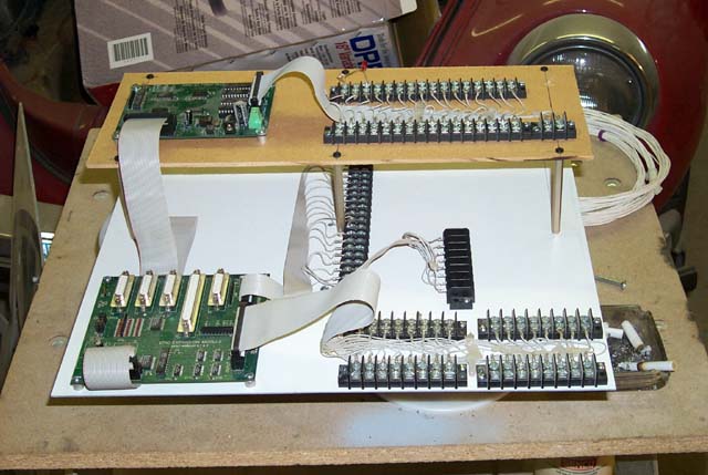
Here's the new mounting board for the basic EPIC modules. On the main
mounting plate the first expansion module is mounted along with the
terminal strips used to break out the 16 analog channels and the main
input matrix (32x8) for the EPIC.
The daughter board contains the 32 point output module and is linked to the
expansion module via a EPIC BUS cable.
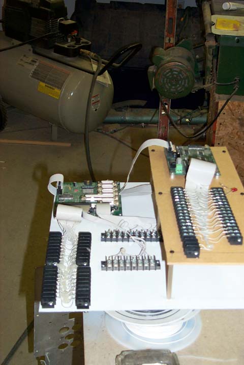
 This gives you a better idea how it's laid out. The white globs on the wiring
is left-over hot-glue that was used when all these cable assemblies were
mounted on the plywood test board.
This gives you a better idea how it's laid out. The white globs on the wiring
is left-over hot-glue that was used when all these cable assemblies were
mounted on the plywood test board.
 Here it sits in it's permanent home. A radar processing module used to be
installed in this space.
Here it sits in it's permanent home. A radar processing module used to be
installed in this space.
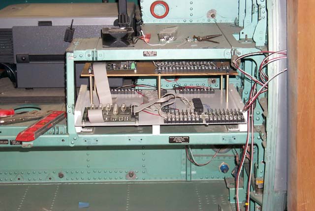 The red, white & black wires you see are the control wiring from the
potentiometers that are connected to the flight controls.
As you can see, the fit is very nice. At least one other EPIC module will
be mounted on this panel.
The red, white & black wires you see are the control wiring from the
potentiometers that are connected to the flight controls.
As you can see, the fit is very nice. At least one other EPIC module will
be mounted on this panel.
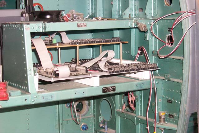 Wiring paths will definately be a challenge here. The wires need to be routed
to produce the least amount of bending stress and cannot rub against any
bare metal edges. Nylon Castle Grommets can be very handy in situations
like this.
Wiring paths will definately be a challenge here. The wires need to be routed
to produce the least amount of bending stress and cannot rub against any
bare metal edges. Nylon Castle Grommets can be very handy in situations
like this.