March 27th, 2002
 This is the first of 2 large terminal wiring boards. Each board can handle
128 individual switch inputs.
This is the first of 2 large terminal wiring boards. Each board can handle
128 individual switch inputs.
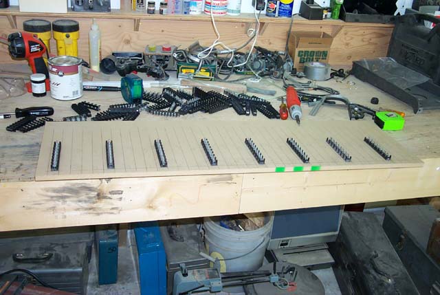
 The board itself is 1/2" MDF (Medium Density Fiberboard). The picture here
show the terminal blocks for the "data bit" connections. The terminals
are labeled "DB0" through "DB7" from top to bottom. They'll be wired into
the 8 position terminal block on the EPIC switch matrix board.
The board itself is 1/2" MDF (Medium Density Fiberboard). The picture here
show the terminal blocks for the "data bit" connections. The terminals
are labeled "DB0" through "DB7" from top to bottom. They'll be wired into
the 8 position terminal block on the EPIC switch matrix board.
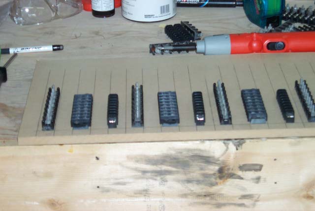
 This is the next stage in the process. The dual row terminal block is where
the matrix diode will be mounted to. The diodes are very important - they
are what allows the EPIC matrix scanner to "see" all the switch positions,
even if many (or all!) or in the closed position.
This is the next stage in the process. The dual row terminal block is where
the matrix diode will be mounted to. The diodes are very important - they
are what allows the EPIC matrix scanner to "see" all the switch positions,
even if many (or all!) or in the closed position.
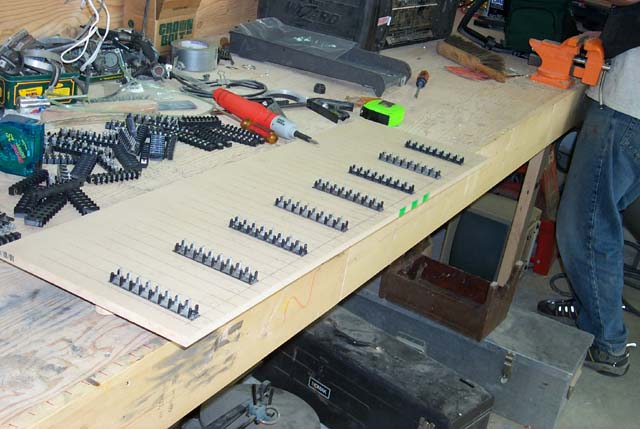
 The last terminal block, the "row" block has been installed. Each one of
these are a single row, 8 position terminal block. All 8 positions have been
wired together to create a "bus". Each one of these will connect to one of
the 32 positions on the EPIC switch matrix board. Each one of these is
described as a "Row". Each EPIC switch "module" has 16 rows and thus will
support 128 switches.
The last terminal block, the "row" block has been installed. Each one of
these are a single row, 8 position terminal block. All 8 positions have been
wired together to create a "bus". Each one of these will connect to one of
the 32 positions on the EPIC switch matrix board. Each one of these is
described as a "Row". Each EPIC switch "module" has 16 rows and thus will
support 128 switches.
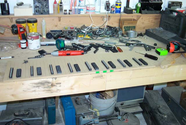
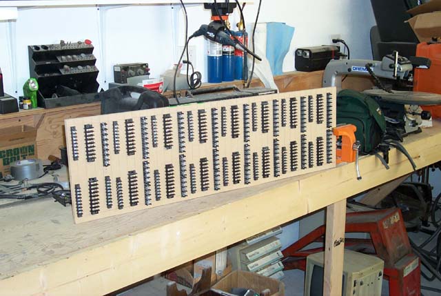 Here is the completed terminal board. As you can see, there are 16 sets of
3 terminal blocks. Each set of 3 is a Module Row. In this case, Module 1,
Row 0 begins at the upper left corner of the board. Row numbers increase
going right. Module 1, Row 8 begins at the lower left corner of the board.
Here is the completed terminal board. As you can see, there are 16 sets of
3 terminal blocks. Each set of 3 is a Module Row. In this case, Module 1,
Row 0 begins at the upper left corner of the board. Row numbers increase
going right. Module 1, Row 8 begins at the lower left corner of the board.
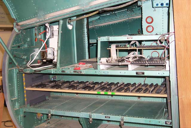 This is what the terminal board looks like in it's "installed" position.
The board slides out for easy maintenance, which is VERY important when
dealing with complex wiring bundles. Eventually the boards will glide on
ball bearing drawer slides, but for this stage of construction, a simple
shelf fit works fine.
This space will hold both of the large terminal boards. A third, much smaller
terminal board will be also located in here (somewhere). The smaller board
will break out the 48 inputs that are present in the scan matrix that's
accessable from the 15 pin joystick connectors on the first expansion module.
This is what the terminal board looks like in it's "installed" position.
The board slides out for easy maintenance, which is VERY important when
dealing with complex wiring bundles. Eventually the boards will glide on
ball bearing drawer slides, but for this stage of construction, a simple
shelf fit works fine.
This space will hold both of the large terminal boards. A third, much smaller
terminal board will be also located in here (somewhere). The smaller board
will break out the 48 inputs that are present in the scan matrix that's
accessable from the 15 pin joystick connectors on the first expansion module.
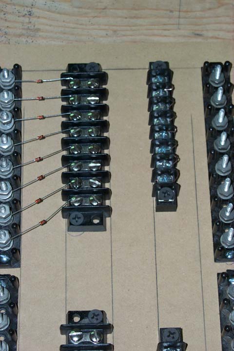 Here is a close-up of how the diodes are installed. The switch wires will go
from the open leg of the dual row terminal block and to the bus-wired 8
position terminal block.
There will be additional wiring to link the diodes as shown in this schematic.
Here is a close-up of how the diodes are installed. The switch wires will go
from the open leg of the dual row terminal block and to the bus-wired 8
position terminal block.
There will be additional wiring to link the diodes as shown in this schematic.