Engine Control Panel Operation
 ENGINE CONTROLS AND INDICATORS
Engine Master Switches
Two guarded engine master switches are on the engine control panel. Placing
either switch to ON (with electrical power available), directs power to
the fuel transfer pumps. Each switch directs power to its corresponding FTIT
indicator and opens is corresponding airframe mounted engine fuel shutoff
valve. The engine master switch must be ON before the corresponding engine
can be coupled to the JFS. Placing the switch OFF decouples the engine from
the JFS. If engine control/essential power is not available, placing an
engine master switch OFF will not shut off its airframe mounted engine fuel
shutoff valve.
Engine Start Fuel Flow Switches (F100-PW-100)
ENGINE CONTROLS AND INDICATORS
Engine Master Switches
Two guarded engine master switches are on the engine control panel. Placing
either switch to ON (with electrical power available), directs power to
the fuel transfer pumps. Each switch directs power to its corresponding FTIT
indicator and opens is corresponding airframe mounted engine fuel shutoff
valve. The engine master switch must be ON before the corresponding engine
can be coupled to the JFS. Placing the switch OFF decouples the engine from
the JFS. If engine control/essential power is not available, placing an
engine master switch OFF will not shut off its airframe mounted engine fuel
shutoff valve.
Engine Start Fuel Flow Switches (F100-PW-100)
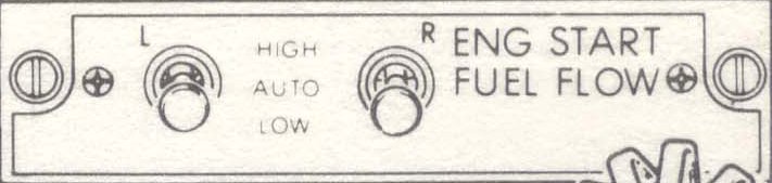 The engine start fuel flow switches, on the right console provide improved
starting performance under certain ambient temperatures and elevation. The
switches have positions of HIGH, AUTO and LOW and are spring loaded to the
lever-locked AUTO position.
HIGH Provides a rich fuel flow for starts and overrides the
automatic sequence.
AUTO Provides a lean fuel flow during normal start. Fue flow is
lean until 30 seconds after the main generator comes on the line then
automatically increases 100 pph (rich).
LOW Fuel flow will drop approximately 100 pph when this position
is selected.
EEC Switches (F100-PW-100)
The L and R EEC (engine electronic control) switches are located on the engine
control panel and provide power to the EEC. The switches have two positions,
ON and OFF.
ON Turns on power to the EEC.
OFF Turns off ECC supervisory control of UC. Exhaust nozzle
remains closed with gear handle down.
ENG CONTR Switches (F100-PW-220)
The L and R ENG CONTR (engine control) switches are located on the engine
control panel and provide power to the DEEC (digital engine electronic
control). The switches have two positions, ON and OFF
ON Turns on power to DEEC for normal engine control.
OFF Turns of DEEC and transfers engine control to secondary mode
(hydromechanical). Afterburner inhibited, engine rpm reduced to
80% max, and exhaust nozzle will remain closed with gear handle down.
JFS Starter Switch
The jet fuel starter switch is on the engine control panel located on the right
console. It has positions of ON and OFF. During engine start, the JFS is
automatically shut down after both engines are started; however, it can be
shut down at any time by placing the switch to OFF.
JFS Ready Light
The JFS ready light is on the engine control panel located on the right console.
The light indicates the JFS is ready to be engaged. The light goes out when
the JFS shuts down.
Generator Control Switches
Two generator control switches, one for each generator, are on the engine
control panel. They are two-position toggle switches with positions of OFF
and ON. The switches are lever-lock type and must be raised up before they
are moved to a new position.
Emergency Generator Control Switch
The emergency generator control switch, on the engine control panel, is a
three-position toggle switch with positions of AUTO, MAN and ISOLATE. The
switch is electrically held in the ISOLATE position.
AUTO Provides automatic activation of the emergency generator
if either or both main generators are inoperative, both
transformer-rectifiers fail, or either or both main fuel boost pumps
fail. After TO 1F-15-764, provides automatic shutdown of the
emergency generator 30 seconds after the first main main generator
comes on the line after a ground start without external power.
On all aircraft, for starts with external power the emergency generator
will not operate as long as external power is connected.
MAN Provides manual activation of the emergency generator.
ISOLATE Restricts the emergency generator to powering the emergency
fuel boost pump and arresting hook and provides power from the
emergency/essential 28 volt DC bus to the emergency air refueling
switch to open the slipway door. On F-15C 83-0035 and up and F-15D
83-0049 and up, the engine rpm indicators are also powered in this
position. In the event of a complete electrical failure, an attempt
to restore the emergency generator may be made by cycling the switch
to ISOLATE and back to MAN.
External Power Control Switch
The external power control switch, on the engine control panel, controls
application of external power to the aircraft electrical buses. An external
power monitor will prevent faulty external power from being connected to the
aircraft system.
NORM Allows the aircraft electrical buses to be energized by
external power if no aircraft generators are operating.
RESET Will establish external power if it is not on the line.
It is spring-loaded to NORM.
OFF Disconnects external power from the aircraft.
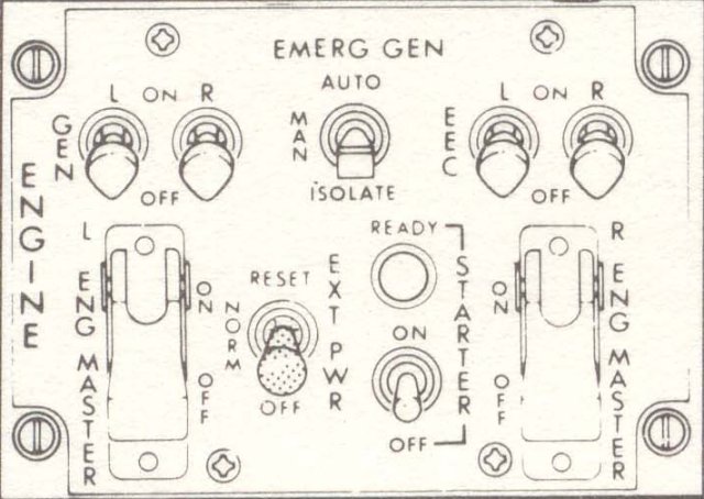
Please note that the drawing at the top shows the engine control panel
as it would be found in an F-15C powered by the F100-PW-100 engine. The
panel in my F-15C is for the F100-PW-220 engine. I've included both text
sections for clarity and completeness.
The engine start fuel flow switches, on the right console provide improved
starting performance under certain ambient temperatures and elevation. The
switches have positions of HIGH, AUTO and LOW and are spring loaded to the
lever-locked AUTO position.
HIGH Provides a rich fuel flow for starts and overrides the
automatic sequence.
AUTO Provides a lean fuel flow during normal start. Fue flow is
lean until 30 seconds after the main generator comes on the line then
automatically increases 100 pph (rich).
LOW Fuel flow will drop approximately 100 pph when this position
is selected.
EEC Switches (F100-PW-100)
The L and R EEC (engine electronic control) switches are located on the engine
control panel and provide power to the EEC. The switches have two positions,
ON and OFF.
ON Turns on power to the EEC.
OFF Turns off ECC supervisory control of UC. Exhaust nozzle
remains closed with gear handle down.
ENG CONTR Switches (F100-PW-220)
The L and R ENG CONTR (engine control) switches are located on the engine
control panel and provide power to the DEEC (digital engine electronic
control). The switches have two positions, ON and OFF
ON Turns on power to DEEC for normal engine control.
OFF Turns of DEEC and transfers engine control to secondary mode
(hydromechanical). Afterburner inhibited, engine rpm reduced to
80% max, and exhaust nozzle will remain closed with gear handle down.
JFS Starter Switch
The jet fuel starter switch is on the engine control panel located on the right
console. It has positions of ON and OFF. During engine start, the JFS is
automatically shut down after both engines are started; however, it can be
shut down at any time by placing the switch to OFF.
JFS Ready Light
The JFS ready light is on the engine control panel located on the right console.
The light indicates the JFS is ready to be engaged. The light goes out when
the JFS shuts down.
Generator Control Switches
Two generator control switches, one for each generator, are on the engine
control panel. They are two-position toggle switches with positions of OFF
and ON. The switches are lever-lock type and must be raised up before they
are moved to a new position.
Emergency Generator Control Switch
The emergency generator control switch, on the engine control panel, is a
three-position toggle switch with positions of AUTO, MAN and ISOLATE. The
switch is electrically held in the ISOLATE position.
AUTO Provides automatic activation of the emergency generator
if either or both main generators are inoperative, both
transformer-rectifiers fail, or either or both main fuel boost pumps
fail. After TO 1F-15-764, provides automatic shutdown of the
emergency generator 30 seconds after the first main main generator
comes on the line after a ground start without external power.
On all aircraft, for starts with external power the emergency generator
will not operate as long as external power is connected.
MAN Provides manual activation of the emergency generator.
ISOLATE Restricts the emergency generator to powering the emergency
fuel boost pump and arresting hook and provides power from the
emergency/essential 28 volt DC bus to the emergency air refueling
switch to open the slipway door. On F-15C 83-0035 and up and F-15D
83-0049 and up, the engine rpm indicators are also powered in this
position. In the event of a complete electrical failure, an attempt
to restore the emergency generator may be made by cycling the switch
to ISOLATE and back to MAN.
External Power Control Switch
The external power control switch, on the engine control panel, controls
application of external power to the aircraft electrical buses. An external
power monitor will prevent faulty external power from being connected to the
aircraft system.
NORM Allows the aircraft electrical buses to be energized by
external power if no aircraft generators are operating.
RESET Will establish external power if it is not on the line.
It is spring-loaded to NORM.
OFF Disconnects external power from the aircraft.
Please note that the drawing at the top shows the engine control panel
as it would be found in an F-15C powered by the F100-PW-100 engine. The
panel in my F-15C is for the F100-PW-220 engine. I've included both text
sections for clarity and completeness.
Operational information on this page taken from TO 1F-15A-1, Change 1 - 15
August 1984
Back to the Systems Operation Index