A Broad Brush Look at...
The F-15 Hydro-Mechanical Control System
- Level I - Flying qualities
clearly
adequate for the mission Flight Phase.
- Level II - Flying qualities ade-
quate to accomplish the mission Flight
Phase, but some increase in pilot work-
load or degradation in mission effec-
tiveness, or both, exists.
- Level III - Flying qualities
such
that an aircraft car. be controlled safely, but pilot workload is excessive or mission effectiveness is inadequate, or both. In short, this means that the basic hydro-mechanical control system must be such that a pilot can complete an air-superiority mission without a bunch of electronic boxes doing it for him.
To better explain Level II handling, an F-4 Phantom (in contrast with the F-15) is incapable of meeting Level II requirements throughout its maneuvering envelope with SAS (or Stab Aug) operating.
Within this article we'll explain how the controls of the F-15 Eagle satisfy this requirement. In later issues of the DIGEST we'll go a little deeper into the system to shed some light on the role of electronics in increasing control capabilities to Level I handling qualities.
COMPENSATOR
Since the Eagle's flight
controls are designed with a fighter pilot's needs in mind, the end
result is a blend of specification requirements and pilot desires.
Any reference to the similarity between a conventional century
series fighter control system would be difficult. It's obvious that
both contain control sticks and control surfaces: however, in the
F-15 it's what's in between that makes the difference.
The part that's "in between"
is what we call the "CSBPC," or Control Stick Boost/Pitch
Compensator. This device is the "brains" of the F-15 mechanical
control system and contains two major assemblies known as the
"Pitch/Roll Channel Assembly" (PRCA), and the Aileron Rudder
Interconnect (ARI).
Since any aircraft responds
differently to a given control surface input, depending upon the
flight condition and extent of maneuvering, considerable
sophistication must be employed within the mechanical control system
to assure uniform response to pilot
commands. The PRCA and ARI
units help the basic hydro-mechanical controls provide the
maneuvering capabilities and handling qualities required to
satisfy the Level II specifications.
Since the applications of
the PRCA and ARI in the Eagle are quite involved, we won't
discuss them in detail at this time. Instead, we'd like to
consider the total hydro-mechanical control system now with
coverage of individual axis and electronic portions in
forthcoming issues of the DIGEST.
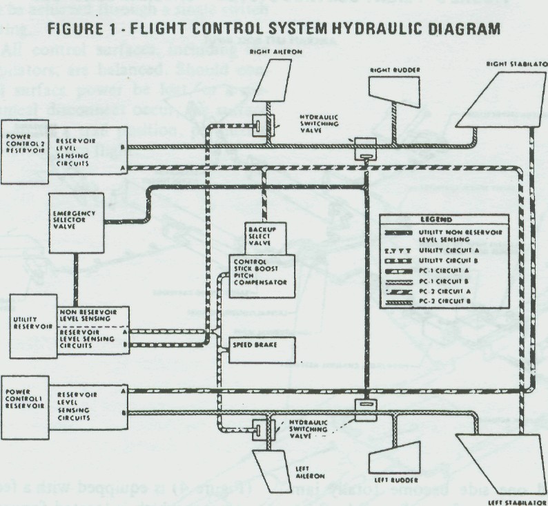
HYDRAULICS
The F-15 control system is
powered by three separate hydraulic systems: Power Control One
(PC-1) driven by the left engine. Power Control Two (PC-2)
driven by the right engine, and a Utility system which contains
two pumps, one on each engine. Each system is provided with a
switchover valve which senses system return pressure. If
pressure falls below a pre-selected value, required pressure is
regained through a switch to another system.
Referring to the hydraulic
system block diagram (Figure 1), you can see which hydraulic
system powers which control system actuator. The PC-1 system
powers the left side of the aircraft plus both stabilator
actuators. The PC-2 system powers the right side of the aircraft
plus redundant power to both stabilator actuators. The Utility
hydraulic system is a backup system and can provide power to
the entire control system. The PRCA and ARI receive their hydraulic
power from the Utility system with PC-2 as a backup. What this all
adds up to is a system that can be safely flown and landed after a
total loss of any two of the three hydraulic systems.
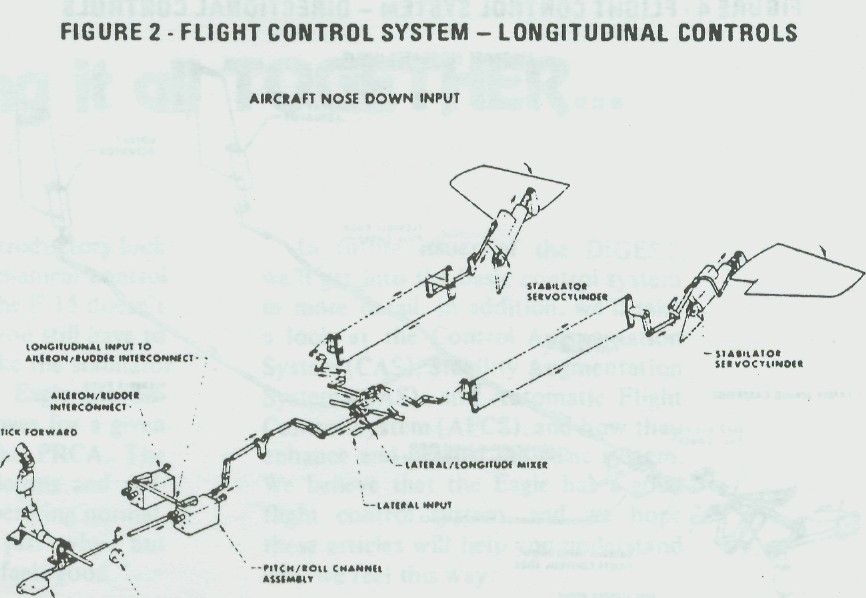
At first glance the Longitudinal Control System (Figure 2) seems to be a conventional system, but as you look at component locations some interesting and important differences become evident.
The feel trim actuator, located in the aft fuselage of most aircraft, is located below the control stick in the F-15. This reduces the amount of linkage, thus reducing control stick dead-band, and lessens overall applied stick force.
Added safety is also obtained should there be a linkage separation downstream of the PRCA. If a separation does occur, a "fly-by-wire" capability is provided by the electronics and the pilot will still have positive feel at the stick. With a manual system such as installed in the F-15, a pilot may not even realize he has a linkage separation since the aircraft will fly and feel the same with or without the problem.
The Pitch/Roll Channel Assembly (PRCA) provides variable mechanical advantage of the pitch control system as a function of airspeed system data.
It also aids in controlling stabilalor de-flection to eliminate the difference between commanded and actual load factors. This feature compensates for trim changes due to such things as speedbrake or flap extensions, external store separations, and aircraft speed changes. The combination of feel trim, variable mechanical advantage, and series trimming gives the pilot, as near as possible, a constant stick force per G and keeps the stick pretty well in the same place in the cockpit throughout the flight. The linkage friction within the PRCA is carefully controlled to reduce control stick breakouts. The feel trim actuator location and shortened linkages to the PRCA and its low linkage friction provide the pilot with smooth, light control stick breakout forces. The PRCA output is hydrauli-cally boosted, eliminating any feeling by the pilot ot excessive frictions downstream of the PRCA. In addition, the hydraulic boost provides a shear force for chips and other foreign objects.
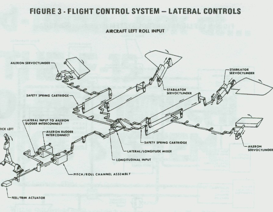
Outside of the PRCA the pitch linkage is fed to a "mixer" linkage where it is combined with roll inputs. These give the stabilator inputs reflective of either pitch or roll. The F-15 stabila-tors arc used collectively tor pitch and differentially for roll.