F-15 Flight Control System
Part III - Lateral Control

By B.P. "PERRY" HOFFMAN/ Senior Engineer, flight Control Section, Avionics Engineering Laboratories
Our last article dealt with the F-15 directional control system; now let's dig a bit deeper, progressing to the lateral control system. Lateral (or roll) control in the Eagle is obtained from simultaneous deflection of conventional ailerons located on the outboard section of each wing and differential stabilators. The amount of aileron/differential stabilator deflection per inch of lateral stick movement is controlled by the Pitch Roll Channel Assembly (PRCA),with scheduling based on both the output of the PRCA pitch boost servo (longitudinal stick position) and airspeed. The net effect is a proper blend of control deflections required for maneuvering throughout the aircraft envelope, and yet the pilot is given approximately the same feel no matter what the flight condition might be. Let's see how some of these requirements are mechanized.

LATERAL TRIM
Referring to Figure 1, follow the lateral linkage from the control stick to the lateral feel trim actuator. Note that the actuator is mounted in parallel with the overall control linkage. This is just a simple way to say that the system linkages are not shortened or lengthened; the trim actuator merely moves the total system.

Fig. #1: Flight Control System - Lateral Controls

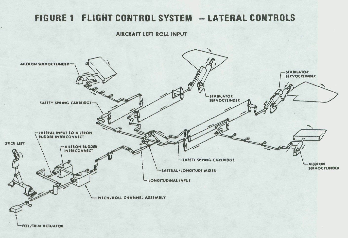
The feel trim actuator performs two equally important tasks: it establishes the zero force position of the control stick and provides the pilot with an artificial feeling of maneuvering stick force. The zero force or "hands-off-stick" position may be varied as the pilot requires by activation of the stick grip button. The trim motor may also be repositioned through operation of the takeoff trim button which drives the actuator to a preset neutral position, streamlining the control surfaces.
 

Simultaneous with actuator travel, electrical signals are generated by a pair of linear voltage differential transformers (LVDT).

These signals are used by the Control Augmentation System (CAS) computers, where they are compared in a preset voltage level detector which turns the actuator off when the. proper level is reached. Another level detector stops the trim actuator at neutral if the takeoff trim button is held depressed.

Outputs from these level detectors are supplied to the takeoff trim indicator light logic in the CAS computers. When this logic sees the same voltage level from all three channels, (roll, pitch, and yaw), the takeoff trim light illuminates, indicating to the pilot that his surface controls are properly positioned for takeoff. These LVDT signals serve yet another function in advising the CAS roll channel of changes in trim commands so that the CAS doesn't defeat pilot-inserted trim. Lateral artificial feel force is provided to the pilot by dual spring gradients within the actuator. For the first inch of lateral stick travel, the force is 5 pounds (plus a 1.0 pound breakout); the gradient then drops to 3.67 pounds per inch of additional stick deflection. The dual spring gradient helps reduce lateral stick sensitivity around neutral. The LVDT signals and CAS circuits are dual redundant, providing a fail-safe operation in which the system shuts down to prevent runaway trim.

ROLL LINKAGE
As it leaves the lateral feel trim actuator, the linkage takes two paths. The first path travels to the ARI on the right-hand side of the airframe. As we discussed in Part II of this series, this input supplies the lateral intelligence to the ARI. The second path continues down the left side of the aircraft to the PRCA which is the "brains" of the F-15 mechanical control system. Figure 2 is a block diagram of the PRCA and shows the data flow within the roll channel of the PRCA.

Fig. #2: PRCA - Roll Channel

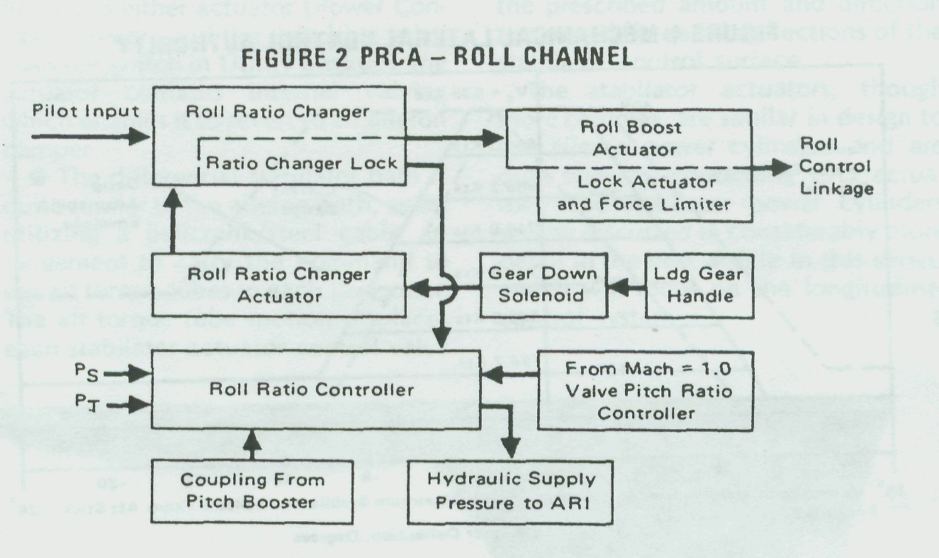
Roll Ratio Changer -- The roll ratio changer, within the PRCA, contains the dual mechanical linkage required to vary the stick-to-aileron/differential stabilators gearing at a ratio of 4:1. Figure 3 explains how a parallelogram ratio changer does its work.

Fig. #3: Simplified Ratio Changer Diagram
The dotted lever 1 pivot D is fixed to the PRCA frame while its pivot E varies with the position of the roll ratio changer actuator. Lever 2 has its pivot C fixed to the PRCA frame while pivot A attaches levers 2 and 3 together.

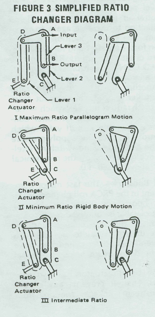
Diagram I shows the ratio changer actuator at maximum ratio as indicated by distances D to A and E to C being identical. Pilot stick inputs to point A displaces the output B by the same amount; that is, a 1:1 ratio. In diagram II, note that the ratio changer has been fully extended, placing pivots E and C over one another. Stick inputs to point A can rotate the linkages about E and C with only a small amount of output displacement for a ratio of 4:1. Diagram III shows an intermediate ratio. In this case, pivot E of the ratio changer actuator can be called upon to vary the ratios as dictated by the air data information fed to it, or by longitudinal control system position.

Presuming you've digested at least a part of that, let's press on. Within the ratio changer section, you'll find a ratio lock. This drives the ratio changer mechanism to the failed ratio in event of a loss of hydraulic supply pressure. In addition, the pilot may select the emergency mode to isolate a suspected malfunction. He does so by placing the Roll Ratio switch to EMERG(ency) which removes hydraulic pressure to the roll ratio channel of the PRCA. The roll ratio repositions itself to about one-half ratio in emergency, or 10° of aileron plus 3° differential stabilator which is more than adequate for normal flight and safe return to base. During emergency operation of the roll channel of the PRCA, the Master Caution light and Roll Ratio telepanel light will illuminate warning the pilot of a problem. Lateral control stick inputs into the PRCA during the transition time are quite heavy
since the actuator is in the process of locking. However, after the short time required to lock, lateral control stick forces settle down to about twice that of a normal operating system. When the Roll Ratio switch is again placed in AUTO(matic), and the hydraulic supply pressure is available, normal system operation is restored.

Roll Ratio Controller/Roll Ratio Changer Actuator — The ratio controller and ratio changer actuator may be considered at the same time since the actuator simply provides the muscle for the ratio controller. The ratio controller receives pitot (Pt) and static (Ps) air inputs from the left hand probe. A cam-operated servo-mechanism controls hydraulic pressure to the roll ratio actuator, repositioning the ratio changer linkage to a new value. Figure 4 illustrates that both air data and longitudinal position affect the ratio controller. Longitudinal stick inputs to the roll ratio controller are the result of mechanical coupling to the roll ratio controller shaft from the PRCA pitch channel boost actuator. The combination of the air data and longitudinal inputs reposition the ratio changer and vary the control stick-to-aileron differential stabilator gearing.

Fig. #4: Mechanical Lateral Control Authority

The only situation in which the ratio controller cannot command the ratio changer actuator to move is when the landing gear handle is positioned to extend the gear. During the early days of F-15 flying,it became apparent that during crosswind landings more than the available roll power was needed to keep the upwind wing from rising. As previously stated (and shown in Figure 4), when the aircraft is slowed to land and the stick is either trimmed or held aft, roll power is "washed out" (the amount of aileron available with full stick is reduced). The problem was re-solved by adding a solenoid valve to the ratio changer actuator which drives the ratio changer actuator to maximum ratio when the landing gear handle is placed in the down position. All production PRCA's have this feature so it is not possible to check aileron/differential stabilator washout on the ground without putting the gear handle up (with hydraulic pressure applied, this just "ain't" a good idea).

A suitable ground check may be made by pulling the PRAD CONT (Pitch and Roll Adjust Device Control) circuit breaker. This circuit breaker removes dc power from the gear down solenoid and aileron washout may then be checked. With the stick at takeoff trim, apply full left roll deflection and note the position of the ailerons.
 

While holding full left stick, slowly pull the stick aft, noting that the ailerons will begin to return to streamline stopping at about a 3 to 5 degree deflection as the longitudinal stick reaches the 3/4 aft travel point. Returning the stick to neutral in pitch causes the aileron deflection to increase again to maximum. The same conditions may be seen for a right stick and for either forward or aft pitch inputs. Resetting the PRAD CONT circuit breaker removes the aileron washout function.

Another signal to the roll ratio controller is a hydraulic input from the pitch ratio controller "Mach = 1.0" sensor. The roll ratio controller contains a hydraulic shutoff valve which controls the hydraulic supply pressure to the ARI. This is the switching intelligence for turning off the mechanical ARI above Mach 1.0.

Roll Booster — The last major component in the PRCA roll channel is the roll boost actuator. The booster control valve is coupled directly to the output of the ratio changer and the valve directs hydraulic pressure to a conventional power cylinder to drive all the downstream linkages external to the PRCA.

The boost actuator has two purposes. First, it prevents any of the downstream linkage friction from being felt at the control stick. Second, the actuator output force is sufficient to provide chip and foreign object shearing forces. In event of a hydraulic failure, or if the pilot selects emergency operation, the boost actuator control valve input arm locks at neutral. Both sides of the boost piston are ported to return pressure, and the actuator functions as a fixed link. Pilot inputs must then physically move the actuator piston as well as all the downstream linkage. This is why the stick forces become a bit higher during emergency operation.

MECHANIZING THE PRCA ROLL OUTPUTS
The output shaft of the roll booster actuator carries the modified lateral commands of the control stick through a conventional system of push rods and bellcranks to the next major component, the lateral/longitudinal mixing linkage.

Mixing Linkage — The mixing linkage receives both lateral and longitudinal control stick inputs, decides which control surface is supposed to move, and pulls or pushes the appropriate control rod to deflect the surface. Figure 5 shows an expanded layout of the mixer which fits together in the shape of a parallelogram. Referring to the expanded view, a lateral input deflects link 1 pushing one aileron rod while pulling the other. At the same time link 2, connected to link 1 by link 4, rotates, deflecting the stabilators differentially. A longitudinal stick input to link 3 rotates it, pulling link 2 which pulls or pushes both Stabilator rods, giving collective Stabilator.

Fig. #5: Lateral/Longitudinal Mixing Linkage

A long, detailed explanation should not be necessary if you keep in mind that during lateral inputs all links move as a unit, rotating about the pivot. During longitudinal inputs, link 1 remains fixed and link 2 moves back and forth rotating about links 3 and 4. Two Linkage Paths — From the mixing linkage there are again two linkage paths.

• The aileron path utilizes push rod linkage to the lateral safety spring cartridge. The safety spring cartridge is connected in series with the lateral control linkage and allows the other aileron (plus differential stabilators) to continue functioning even though the linkage in one wing is hopelessly jammed. The safety spring cartridge is attached to a system of bellcranks and cables, carrying the lateral command to the wing root area. Push rods and idler bellcranks then carry the command to the aileron power cylinder control valve which ports hydraulic pressure to a single system actuator, deflecting the control surface.

The aileron power cylinder is a bit different than those used on previous McDonnell-built aircraft. The actuator body is fixed to the airframe and the linear operating ram is attached to the control surface. A mechanical feedback arm is connected between the ram and control valve to stop actuator travel when the input command is satisfied. In the event of total hydraulic loss to either actuator (Power Control is primary and the switching valve does not switch in Utility backup), the actuator contains internal valving which enables it to revert to an aileron damper.

• The differential stabilator path is quite similar to the aileron path, again utilizing a bellcrank/steel cable arrangement to carry the command to the aft torque tubes in each tail boom. The aft torque tube motion displaces each stabilator actuator control valve the prescribed amount and direction to cause differential deflections of the stabilator control surface.

The stabilator actuators, though more complex, are similar in design to the aileron power cylinders and are dual systems, containing CAS actuators. The stabilator power cylinders will be discussed in considerably more detail in the next article in this series, which will focus on the longitudinal control system.