F-15 Flight Control
System
Part IV - Longitudinal Control
By B. P. "PERRY" HOFFMAN/Senior Engineer, Flight Control Section, Avionics Engineering Laboratories
PITCH FEEL TRIM ACTUATOR
Beginning at the extreme left of the diagram, the first major component affecting control stick operation is the pitch feel trim actuator. It is designed to be in parallel with the total longitudinal linkage.
The zero-force or hands-off stick position is varied when the pilot presses the pitch trim switch on his stick. The pitch trim actuator moves the trim position of the control stick and linkage to satisfy pilot requirements. The only force the pilot normally feels when he moves the stick is generated by a dual-spring cartridge which is part of this trim actuator. These dual springs give the stick a higher force per inch displacement near the trim position and a reduced force per inch for larger stick inputs. This reduces the force a pilot has to hold for sustained high g maneuvers.
Electrical commands from the control stick trim switch or the takeoff trim button extend or retract the trim actuator. Linear Voltage Differential Transformers (LVDT) are mounted on the actuator and generate electrical signals which advise the CAS computer of the new trim position so that the CAS will not try to defeat the pilot-desired trim change. These same signals are also used by preset level detectors which shut the trim actuator off before the actuator reaches its mechanical limits.
When the takeoff trim button is depressed, the trim actuator drives to a pre-determined position dictated by preset detectors within the CAS computer. The electrical sensors and components associated with the trim system are dual so that a loss of any one element causes the trim to shut down, preventing a runaway trim condition for a single failure.
Moving aft from the trim actuator, there
is a lead weight on an idler arm. This is not a "bobweight" for
generating stick force per g, as is the case in the F-4, but is
there simply to balance the control system so that sudden
acceleration or deceleration of the aircraft does not produce stick
motion.
To begin with, let's break the PRCA pitch channel into its components (Figure 2) and see how each affects the longitudinal controls. The input rod offers two linkage paths with the main path tying directly into the ratio changer linkage, and a second input being supplied to the Load Factor Sensor portion of the Pitch Trim Controller.
Pitch Ratio Changer -- The pitch ratio changer utilizes dual redundant parallelogram linkage identical in operation to the roll ratio changer described in our last DIGEST article on lateral controls. The only operational difference is that the pitch ratio changer gearing utilizes a 6:1 ratio, where the roll ratio changer utilizes a 4:1 ratio.
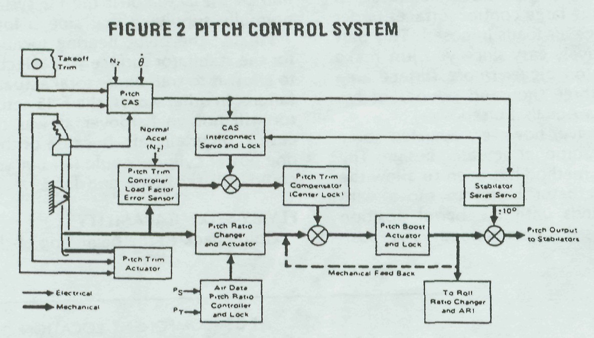
Pitot (Pt) and static (Ps) information is supplied from the left-hand probe to the ratio controller bellows assembly, repositioning a cam-operated valve supplying hydraulic pressure to the ratio changer actuator. The ratio changer actuator then drives the changer linkage, varying the stick-to-stabilator gearing as required.
If hydraulics are lost to the PRCA, or if the pilot selects the EMERC position of the pitch ratio changer by actuation of the Pitch Ratio switch, the pitch ratio changer will drive to its failed position. In the failed mode, the gearing ratio is one-half of its maximum value and all other functions (PTC and Boost) are inoperative.
Two additional functions are associated with the ratio changer (one is no longer used, but a note of explanation is in order in case you see it on a schematic diagram). Early in the program there was a gear down valve which drove the pitch ratio changer to maximum (for landing control) when the nose gear proximity switch actuated. The disadvantages seemed to outweigh the advantages, so the valve has been deactivated on current Eagles and the valve will not be in future PRCA's. For the maintenance man, this is a great help since he can simply place the Pitch Ratio switch to emergency and check the fail mode without having to simulate a gear up condition.
The second function is a safety feature controlled by the pitch ratio changer actuator. If a hardover failure of the pitch trim controller occurs at low pitch ratios, the pitch CAS is inoperative, longitudinal control could be lost. To guard against this possibility, a valve within the ratio changer actuator is opened when the actuator approaches the minimum ratio position. This valve supplies hydraulic pressure to an interlock piston within the pitch trim compensator, keeping it at a position where adequate control is always available.
The output of the pitch ratio changer is fed to the pitch boost actuator servo valve. The boost actuator output is mechanically linked back to the servo valve input, closing the loop. The boost actuator output also feeds the downstream linkage, which deflects the stabilators and drives the linkage scheduling the roll ratio controller and the ARI. As you will recall from our previous articles, the pitch output is used in roll to schedule the roll ratio as a function of angle of attack. Yaw is affected by this also, since yaw gain increases as roll gain decreases. No more rudder rolls, guys; all you need for high angle of attack maneuvering is a lateral input from the stick.
Pitch Trim Controller —
The pitch trim controller adds or subtracts stabilator deflection to compensate for such aircraft variables as increases or decreases in airspeed, speed brake/flap extensions, or changes in loading. These changes are introduced without movement of the control stick. These combined PTC and pitch ratio changer outputs result in a nearly constant stick force and stick position per g within the Eagle's operating envelope (about four pounds of stick force results in one-half inch of stick displacement, producing a load factor of one g). The name given this feature is "series trim." The concept is not new; it's been tried on several previously-built aircraft. The uniqueness of this feature in the F-15 lies in the fact that it works, and does so without electrical inputs.
Stick inputs are fed into a high-class, accelerometer-controlled servo loop known as the load factor error sensor (LOFES), a part of the PTC. This stick input establishes the neutral or zero point it works around. For example, let us assume that a pilot, or the trim actuator, is holding the stick in a position commanding a load factor of one g. Any subsequent deviation from that setting will be sensed by the PTC accelerometer which will valve hydraulic pressure to the pitch trim compensator piston, repositioning the piston and commanding the required amount of collective stabilator to keep the aircraft at one g. This series trimming capability is true for disturbances created by flap, speedbrake, and landing gear extensions. Acceleration and deceleration are also compensated for, producing an essentially neutral speed stable airframe. Since the trim change we've described is "series," no stick movement is noted.
A rapid warm-up valve has recently been added to the PTC. Hydrome-chanical devices such as the PTC utilize extremely close tolerances in their construction and don't want to work well when the surrounding metal and hydraulic oil are cold. Because of this, a viscosity sensing bridge coupled to the PTC pressure inlet bypasses the input hydraulic oil through a small orifice which speeds the warm-up process and allows normal control operation sooner. All production PRCA's contain the warm-up fix, as do most flight test units.
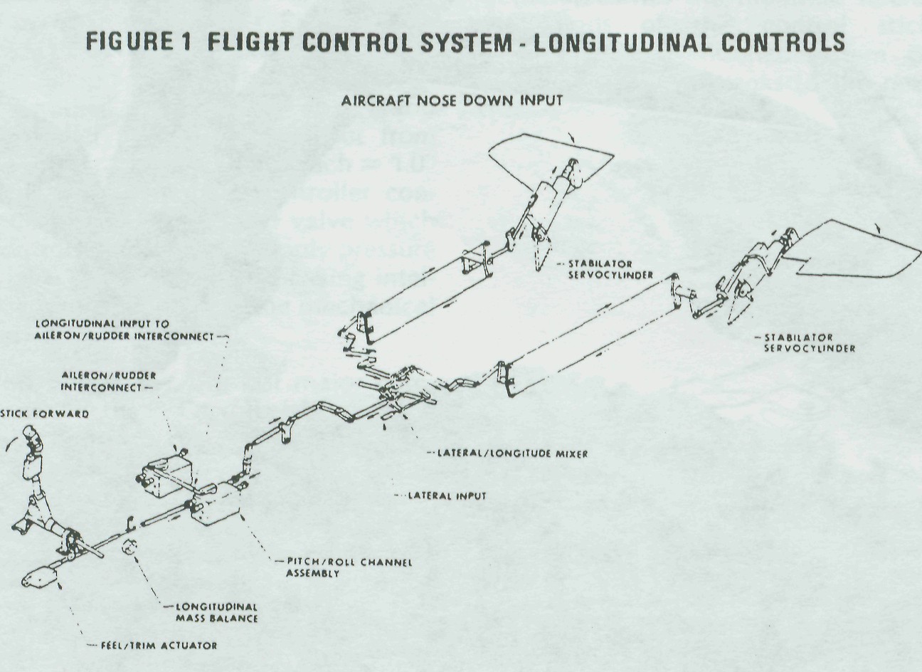
LINKAGE
Control rods carry the PRCA output to the mixer linkage. The mixer linkage combines the pitch command with the roll system signals to drive the stabilator (a diagram of the mixer linkage was presented in the article about roll control in the last issue). Then a system of dual cables and bell-cranks extends along the major length of the fuselage to the aft torque tube. The aft torque tube carries the pitch commands directly to both stabilator control valves, causing actuator displacement and resultant stabilator deflection.
