F-15 Flight Control System
Part VI
Pitch Control Augmentation

By B. P. "PERRY" HOFFMAN/Senior Engineer, Flight Control Section, Avionics Engineering Laboratories

To conclude this series of articles about the F-15 Flight Control System, let's look at the Pitch portion of the Control Augmentation System (CAS) and the Attitude/Altitude Hold modes. Please stay with me to the end; while I've attempted to remove most of the mysteries surrounding this complex electronic system, it hasn't been easy and I hope we all don't get too confused.

Pitch CAS/Single Channel - The operation of the pitch channel electronics is similar to yaw and roll in that Pitch CAS performs two functions. First, conventional stability augmentation improves ride comfort by reducing or eliminating undesirable aircraft motions from disturbances such as wind gusts. The second operation provides the pilot with precise control of aircraft performance by measuring the aircraft response to a given command, and adding or subtracting stabilator deflection as required to match the command to the "ideal."

Stability Augmentation - As shown in Figure 1, the prime sensor used for damping the unwanted pitch oscillations is the pitch rate gyro. When the aircraft receives a change in its flight path, the resultant rate of change is sensed by the rate gyro. A corrective signal is generated by the pitch rate sensor and is fed to a buffer demodulator, then a rate canceller (which eliminates steady signals), and to a variable limiter (which eliminates switching transients during landing


Fig. #1: Pitch CAS Block Diagram

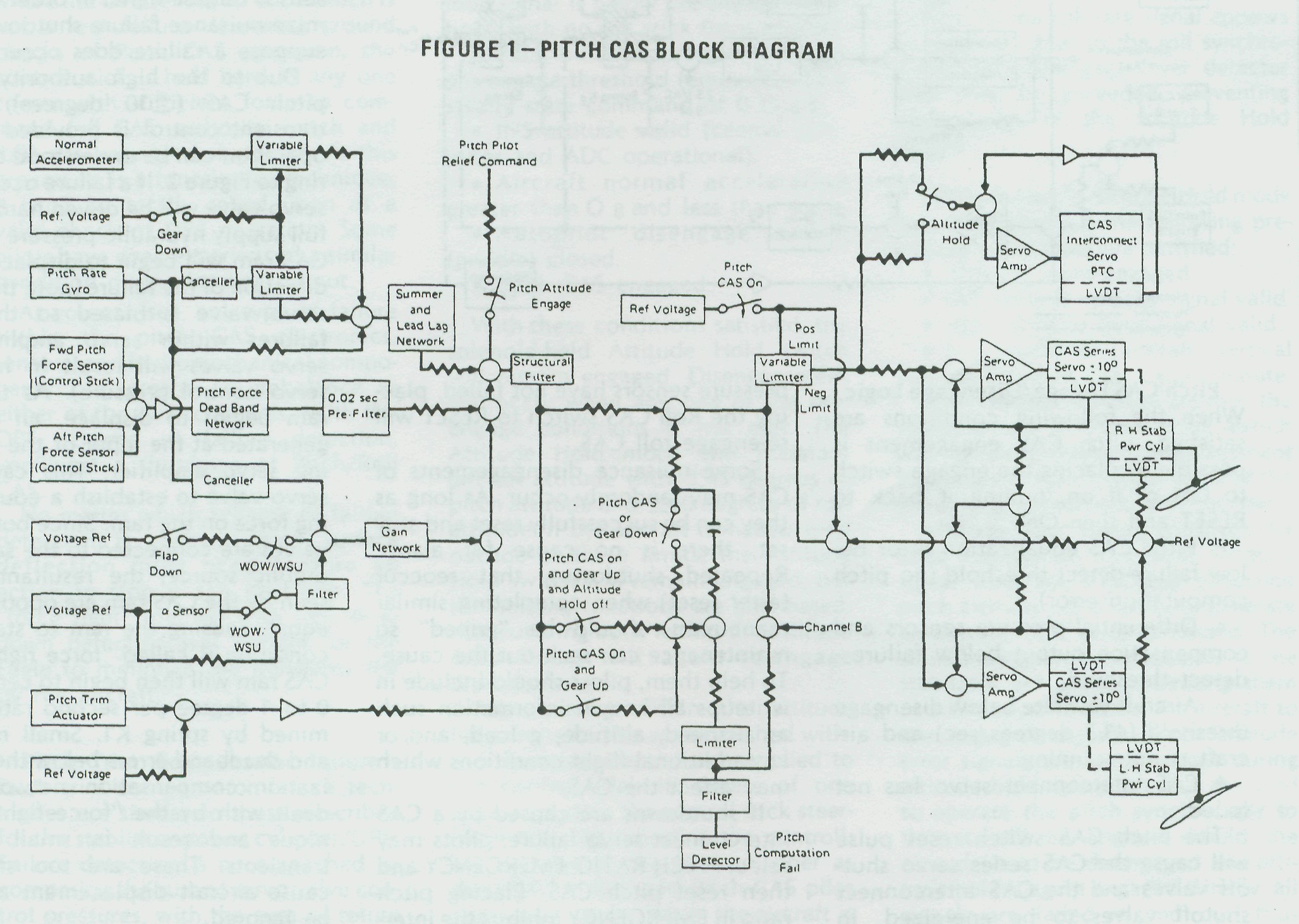
gear operations). The rate signal is then summed, shaped, and sent to a structural filter which reduces frequencies that would cause coupling to the airframe, producing unwanted stabilator oscillation.

The variable limiter performs two functions. When the Pitch CAS switch is reset, the limiter slowly increases CAS authority from zero to 10 degrees. Secondly, it forces the roll and pitch channels to share the 10 degree authority over the stabilator actuators by limiting the amount of CAS series servo deflections either channel can command when the mechanical pitch deflection is greater than 18 degrees nose up.

The modified corrective rate signal is then applied to a servo amplifier which electrically commands the servo valve to extend or retract the 10 degree CAS series servo (internal to the stabilator power cylinder), repositioning the main power cylinder control valve, and porting hydraulic pressure to the power cylinder main ram piston. When the main ram piston deflects, it repositions the stabilator control surface in a direction to stop the unwanted airframe disturbance. An electrical follow-up signal is generated by the 10 degree CAS series servo Linear Voltage Differential Transformer (LVDT) which opposes the corrective rate signal input. When sufficient series servo deflection is obtained to match the rate signal input, series servo deflection stops. The aircraft rate of change in its flight path will grow smaller, and the follow-up LVDT signal starts to return the series servo to neutral. When the aircraft flight path is again stabilized, the rate signal is zero and the CAS series servo is at neutral.

A condition where no aircraft rates are being generated and corrective action is being taken by pitch stab aug is pretty hard to come by. The pitch stab aug is constantly working to maintain a stable airframe. (For the sake of simplicity, we only considered a single channel rate disturbance.)

Pitch Control Augmentation - Looking again at Figure 1, find the forward and aft pitch force sensors (F-15A or TF-15A). Longitudinal stick force commands from one (or both) control stick force transducers are summed together and fed through a deadband/ dual-gradient circuit (prevents over-sensitivity near null and reduces stick forces during sustained high "g" maneuvers). The resultant stick force command then goes through a 0.2 second pre-filter for smoother system responses to sharp pilot inputs (this improves tracking characteristics). The shaped command signal is then sent through the same structural filter as the stab aug rate signal, and on to the variable limiter. The variable limiter, used for stab aug and pilot commands, has the same reason for being in the circuit and operates the same as was explained in the stab aug section.

The pilot command is then sent equally to the left and right servo amplifiers which electrically command the servo valve to extend or retract the 10 degree CAS series servo, repositioning the main power cylinder control valve, and porting hydraulic pressure to the power cylinder main ram piston. Deflection of the piston repositions the stabilator control surface in the direction desired. Two LVDT follow-up signals are generated by the movement of the stabilator power cylinder. The main ram LVDT signal provides the intelligence for the variable limiter, telling the limiter just where the stabilator control surface is located. The other follow-up signal is again the CAS series servo position and stops series servo displacement when the input signal level is matched. Aircraft response to a pilot's stick force command is measured by the pitch rate gyro and normal accel-erometer sensor outputs. These signals meet at the summing/lead lag network. If the measured response after summation does not agree with the control stick force command, the difference is fed to the stabilator actuators, adding or subtracting control surface deflection until the difference is zero. This is called "blending of command and surface deflection" to achieve the ideal aircraft response.

Up to now, we've considered an aircraft with landing gear and flaps up. When the gear handle is positioned down, normal acceleration signals and the pitch rate canceller circuit are eliminated. The removal of normal acceleration is necessary to get rid of transients due to aircraft impact with the runway. Removal of the pitch rate canceller circuit at the same time insures stable longitudinal control during approach and landing. The reduction of these two signal levels is achieved through variable limiters which have a one-second time constant for fade in or out.

Angle-of-attack signals are also used by the pitch CAS to inhibit stalls andmatch the pitch CAS to the mechanical control system stabilator command characteristics during high angle of attack maneuvers.
The stall inhibiting circuit subtracts a portion of the pilot command signal proportional to angle of attack above a threshold determined by flap position. The threshold is higher with flaps down due to added lift which increases the stall boundary. Pitch rate signals are added to the angle-of-attack signals to provide stall inhibit anticipation during rapid maneuvers. The angle-of-attack signal is switched to a pre-set value by the weight-on-wheels switch, or by wheel spin-up signals from the anti-skid sensors, removing stall inhibition during ground operation.

Pitch trim signals are also fed into the pitch CAS to tell the system what trim value the pilot requires. If this trim signal were not present, any manual retrim selected by the pilot would be defeated by the CAS returning the aircraft to the original trim position. Pitch CAS commands are also used to deflect the CAS inter-connect servo, located in the Pitch Trim Compensator module of the PRCA. These commands serve two functions. First, they insure that the mechanical and the CAS systems are tracking each other, minimizing any disagreement that may exist if the pitch CAS disengages and the mechanical system takes over. The second feature allows the CAS interconnect servo to carry an offset from null, allowing the CAS series servo (within the stabilator power cylinder) to maintain its full ±10 degree authority.

Pitch CAS Engage/Disengage Logic -
When the following conditions are satisfied, pitch CAS engagement is possible by placing the engage switch to ON or if on, pulling it back to RESET and then ON.

• Pitch CAS equalization error below failure-detect threshold (no pitch computation error).

• Differential pressure sensors and compensation output below failure -detect threshold.

• Aircraft yaw rate below disengage threshold (41.5 degrees/sec) and aircraft is not spinning.

• CAS interconnect servo has not failed.

The pitch CAS switch reset pulse will cause the CAS series servo shut-off valves and the CAS interconnect shutoff valves to be energized. In addition, the differential pressure sensor failure - detect circuit and equalization integrator will be activated.

Activation of the series servo and interconnect servo shutoff valves latches the necessary logic to keep the shutoff valves engaged. Simultane-ously, another latch circuit activates the pitch CAS engage limiter, fading from 0 to 100% authority (± 10 degree series servo), extinguishing the tele-panel fail light.

Disengagement of pitch/roll CAS occurs if any of the pre-engage conditions indicate a failure. Roll CAS may be reset if the failure has not occurred within the stabilator power cylinder or power cylinder wiring.

As long as the CAS series servos and differential pressure sensors have not failed, placing the Roll CAS switch to RESET will re-engage roll CAS.

Some nuisance disengagements of CAS may randomly occur. As long as they can be successfully reset and stay set, there is no cause for alarm.
Repeated shutdowns, that reoccur (after reset) when completing similar maneuvers, should be "griped" so maintenance can seek out the cause. To help them, pilots should include in writeups all known information such as airspeed, altitude, g load, and/or any additional flight conditions which may affect the CAS.

If shutdowns are caused by a CAS interconnect servo failure, pilots may select PITCH RATIO EMERGENCY and then reset pitch CAS. Placing pitch ratio in EMERGENCY inhibits the interconnect failure detect logic. Pilots then have the option of flying at about one-half mechanical pitch ratio without hydraulic boost from the PRCA (this means you'll have higher stick forces). Also, mechanical ARI will be inoperative. With pitch ratio EMERGENCY selected, and an operational pitch CAS, sufficient longitudinal control is available for most maneuvers including adversities during the landing phase. Whatever method you select, leave pitch CAS shut down with full mechanical ratio (plus operational series trim from the pitch trim controller), or select emergency pitch ratio and reset pitch CAS. Slow down to a reasonable "q" before experimenting.

Failure Detection - The primary means of failure detection for Pitch CAS is the monitoring of voltage levels generated by a differential pressure sensor located in each stabilator power cylinder. Normally the voltage level will be zero (no failures) which satisfies an equalization integrator circuit of the CAS and shutdown will not occur. A lag network is employed to filter the differential pressure sensor output signal in order to minimize nuisance failure shutdowns. But suppose a failure does occur?

Fig. #2: Pitch/Roll Servoloop


Due to the high authority of the pitch CAS (±10 degrees), failure transient control is provided and its operation can be understood by referring to Figure 2. If a failure occurs, one servo valve will be driven hardover by full supply hydraulic pressure and the CAS ram will begin to displace in the direction of the failure (note that each servo valve is biased so that null failures within servo amplifiers or servo valves will result in hardover servo control pressure). As the CAS ram begins to displace, an error is generated at the input of the remaining servo amplifier. This causes its servo valve to establish a counteracting force on the ram. Since both servo valves are connected to the same hydraulic source, the resultant forces seen by the CAS ram are opposite and equal, causing the ram to stall. This condition is called "force fight." The CAS ram will then begin to center at a 0 to 1 degree per second rate determined by spring K1. Small mistrack and deadband errors below the equalization compensation networks are dealt with by the "force fight" technique and result in small engage transients. These are too small to cause aircraft displacement and can be ignored.
 
Looking again at Figure 2, note the differential pressure sensor (DPS) ram and its associated connections. With no failures, pressure C1 and C2 on the right hand side of the DPS ram are equal and balance the combined pressures of Ps + Pr and spring K2 on the left side of the DPS ram. In this condition, equilibrium exists (no motion of ram) and the equalization compensation integrator output is zero (CAS remains set, no failures).

If pitch CAS component failure occurs, such as described in the "force fight" explanation, the equilibrium of pressures C1 = C2 on the right side of the DPS ram are upset and the DPS ram begins to drive slowly hardover. The DPS, LVDT signal is fed to the equalization compensation integrator which starts to slew in a direction to reduce the LVDT signal to zero. If the integrator signal has not reached zero in three seconds, a shutdown pulse is generated by the CAS and both stabilator ±10 degree series servo shutoff valves are deenergized. Controlled orifices and spring-controlled locks center the CAS and DPS rams.

There is one normal condition where the DPS senses an error which is not a real failure. If during ground checks of Pitch CAS operation, the control stick is held hard in any one corner with sufficient force to command full CAS authority (pitch and roll), you may get a shutdown. As this procedure is a function of technique, it can't be totally relied upon as a valid check of DPS operation. Some pilots have even experienced a similar condition during landing rollout.

As you can see, any type of failure within the pitch CAS electronics, sensors, and hydromechanical components can create an imbalance in either of the dual channels. With the DPS scheme of failure detection, you'll get a shutdown of Pitch/Roll CAS.

No matter which scheme of failure detection is chosen, some surface deflection must occur before an action to stop it can be taken. The "force fight" method with DPS shutdown detection was chosen for the Eagle to minimize the transients felt by the aircraft.

Pitch Trim Compensator Failure -
Pitch trim compensator failure techniques are similar to those described for the stabilator power cylinder/DPS. Failure detection is accomplished by comparing the sum of servo valve control pressures, with the sum of return and regulated hydraulic supply pressures. A spring-loaded differential pressure spool is employed to compare the pressure, and if the hydraulic pressures are sufficient to overcome the detent spring loads (component failure of PTC interconnect servo), the ram deflects and opens redundant failure-detection switches. Opening of any of the PTC switches creates a failure pulse which shuts down the pitch CAS Pilot action with a PTC failure was discussed earlier.

Equalization of PTC failure detection is unnecessary since dual channel pitch CAS commands are averaged at the servo amplifier. This assures the same command to each channel and the PTC servo gains are considerably lowered. As a result, channel mistrack displacements are higher, but since the servo drives the PTC at a slow rate, the resultant transients are acceptable.

Roll/Pitch Pilot Relief Modes (Attitude Hold) - Attitude Hold modes may be engaged if all the following pre-engage conditions are satisfied:

• Roll attitude interlocks are present (yaw/roll CAS engaged and roll outer loop signal is below pre-engage threshold) with no roll stick force applied.

• Pitch outer loop signal is below pre-engage threshold (equivalent to a steady state command of 0.25 g.)

• INS attitude valid (central computer and ADC operational).

• Aircraft normal acceleration greater than O g and less than +4 g.

• Autopilot disengage switch (paddle) closed.

• Pitch CAS engaged.

With these conditions satisfied, the solenoid-held Attitude Hold switch will remain engaged. Disengagement will occur when any one of the pre-engage conditions is not met. The Attitude Hold mode will maintain aircraft attitude with ±45 degrees of pitch attitude and ±60 degrees of roll attitude. If the aircraft is maneuvered outside of these limits, the Attitude Hold switch will remain engaged, but the holding functions are eliminated. Maneuvering back within the attitude hold limits will again re-engage attitude hold.

Maneuvering within the attitude hold limits can be accomplished without disengagement. Force applied to the control stick in excess of one pound actuates the control stick steering mode, repositioning the controlling surfaces in the same manner as described in Roll and Pitch CAS pilot command inputs. While the aircraft is maneuvering, the Pitch and Roll Attitude Synchronizer is unlocked and allows synchronization to the new attitude commanded by the pilot. When sticks force is reduced below one pound, Attitude Hold modes re-engage.

Both the Roll and Pitch Attitude Hold modes have solid state synchronizers. These follow the attitude information from the INS platform attitude gyro, keeping the attitude signals below the pre-engage threshold limits.

There is an additional input to the roll synchronizer, roll rate, when the Attitude Hold mode is engaged and the pilot is maneuvering the roll control stick steering. Under this condition, the roll rate signal is sent to the roll synchronizer, causing it to lead the changing roll attitude. If this slight lead were not used, pilots would experience "roll rebound" or, if the stick was released at 30 degrees of right wing down for instance, the aircraft would roll back to 25 degrees because the roll synchronizer did not keep up with the aircraft roll rate. The rate signal is switched out prior to engagement of the Attitude Hold switch. As the roll rate signal appears as an error signal to the roll synchronizer, the pre-engage lever detector limit may be exceeded, preventing engagement of the Attitude Hold modes.

(Altitude Hold)-Altitude Hold mode may be engaged if the following pre-engage conditions are satisfied:

• Altitude Hold engaged.

• INS vertical velocity signal valid.

• ADC altitude error signal valid.

• Magnitude of aircraft vertical velocity less than 2000 feet per minute.

When these conditions are met, the solenoid-held Altitude Hold switch will remain engaged. Disengagement of altitude hold will occur if any of the pre-engage conditions are not met.

Altitude error signals from the Air Data Computer, a vertical velocity signal from the INS, and cancelled pitch attitude are blended to generate an altitude hold error command. The resultant signal is sent equally to the stabilator actuators, deflecting them in a direction to return the aircraft to the engaged altitude. Pitch attitude error signals are switched out during altitude hold operation, but are used to operate the pitch synchronizer so that it will be aligned should the altitude hold be disengaged and attitude hold is again engaged. Finally, all signals are faded in and out, thus minimizing transients.