F-15 Flight Control
System
Part V - Yaw and Roll Control Augmentation
The Control Augmentation System (CAS) consists of two distinct functions. The first is our old friend, the Stability Augmentation System, otherwise known as Stab Aug or SAS. For those old-timers who can remember far enough back, this used to be called a Damper. The Stab-Aug, or Damper, portion of the F-15 CAS is designed to help stabilize the airframe, compensating for unwanted motion which might occur as a result of wind gusts or disturbances.
The second CAS function is its Control Stick Steering mode. This measures, compares, shapes, and smooths out pilot stick and pedal inputs allowing precise and comfortable control throughout the maneuvering envelope
Why is CAS desirable? Well, we know that the F-15 airframe is basically stable, and that the manual flight controls are designed to give Level II handling without augmentation. (Military Specification MIL-F-8785B de-fines Level II handling as "flying qualities adequate to accomplish the mission Flight Phase, but some increase in pilot workload or degradation in mission effectiveness, or both, exists.") Despite the basic stability of the Eagle, various flight conditions and varieties of store loadings could result in some pretty touchy handling situations were it not for the CAS. In addition, the CAS provides safe control of the aircraft should the basic mechanical system suffer failure or battle damage such as foreign object jams or shot-away linkage.
The bulk of this article will be concentrated upon the yaw and roll CAS (you'll see, shortly, that these two functions can't be separated). The pitch CAS will be the subject of a future article.
YAW CAS
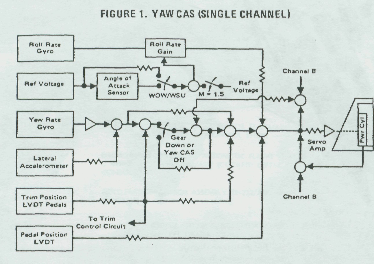
Sideslip Control and Damper - Precise sideslip control is provided during maneuvering by the yaw CAS. Referring to the yaw channel block diagram (Figure 1), you'll see a Rudder Pedal Position Linear Voltage Differential Transformer (LVDT). As the pilot applies force to the pedals, the me-chanical system begins to deflect the rudders. At the same time, the pedal position LVDT generates an electrical signal. As the aircraft responds to the pedal input, the yaw rate gyro and the lateral accelerometer will sense this motion.
Elimination of Steady-State Sideslip - A
circuit was added to reduce uncommanded and persistent sideslip (due
primarily to rudder linkage friction or hysteresis) during
supersonic flight and following a maneuver. The combined lateral
acceleration and yaw rate sensor feedback voltages are compared with
the rudder trim position and the combined output is used by the
Proportional plus Integral (P + I) circuit to apply rudder surface
deflection in a direction to eliminate the sideslip. With a maximum
authority of ±3.75 degrees rudder, pilots can expect the ball to be
pretty well neutral during flight.
There is, however, one disadvantage to the P + I circuit. If rudder surface hangup exceeds the P + I authority, yaw CAS cannot automatically trim the aircraft to zero sideslip. Thus, some manual pedal trim may be required to make up the difference, reducing sideslip to minimum. Manual trim should be applied slowly, or in small amounts with waiting periods, since the new pedal LVDT position affects the integration of the P + I circuit. If this procedure is not followed, it may appear to the pilot that he is chasing the trim.
Pilots can expect to see yaw trim changes varying in magnitude with different aircraft anytime the landing gear is extended or yaw CAS is disengaged. Both of these actions drive the P + I integrator to zero, introducing a yaw transient. So we may have solved the supersonic sideslip problem but created a problem at yaw CAS shutdown.
Maintenance personnel will have to locate and reduce system friction to a minimum. A good source of system friction can be found in the flexible cables. Here are a few points to keep in mind:
• Any kinks or rough spots are
cause for cable replacement.
• At any attach point such as bellcranks or ARI output rods, attempt to line up the cable end exactly with its attach point. In other words, reduce any apparent side load; the nature of the ribbon cable is to increase friction loads as side force is exerted on the ends.
• Make changes in direction with as large a radius as possible with only minor twists.
To summarize, problems will go away when mechanical rudder linkage is kept friction-free.
All three CAS channels utilize a dual-channel "Fail-Off" system. There are several things that would cause the failure detection circuitry to shut down CAS: if spin is evident (yaw rate exceeds 41.5 degrees/second); a malfunction unbalances the yaw computation circuits; an imbalance between the rudder actuators; and failure of the rudder actuator shut-off valves. Let's amplify a bit on these situations -
• If CAS is causing or aggravating the spin mode, we want CAS off. Therefore, any yaw rate in excess of 41.5 degrees/second will cause yaw CAS to shut down. Roll shuts down as a result of yaw shutting down and pitch follows if the high yaw rate continues for a period of longer than 120 milliseconds.
• Yaw CAS will shut down for malfunctions which unbalance the yaw computation circuits. This may result from differences in one of the dual yaw rate gyros or lateral accelerometer output voltages which exceed a preset level. The system will also be shut down by an electronic failure within the yaw computation circuits.
• A shutdown of yaw CAS will occur if a problem in the system causes one rudder hydraulic actuator to mistrack the other by approximately four degrees for a period of one second or longer.
• The final cause for shutdowns applies to production computers Part Number 275E514G3 which will be installed effective F-15 ship 61 and TF-15 ship 14. Circuitry has been added to these computers which senses open wiring to the rudder surface actuator shutoff valve or a failure of the actuator shutoff valve itself. In the older C2 computers, an open in shutoff valve wiring renders the yaw CAS inoperative; however, the roll CAS will not be shut down and the roll and yaw CAS telepanel lights remain out. Because of the inoperative shut-off valve, electrical signals from the CAS will not affect the rudders; the only rudder movement will come from mechanical inputs. Since the rudders will not mistrack in this mode, there will be no shutdown.
During preflights (maintenance and aircrew), ground personnel should double check to insure that yaw CAS inserts an additional 50 percent (or 15 degrees) of rudder surface deflection, making a total surface movement of 30 degrees (these figures are approximate).