January 25th, 2003
The original throttle control interface that I designed turned out to
be an almost-ran. The problem was that the slide potentiometers that I
obtained for the mechanism weren't long enough. I had incorrectly measured
the pushrod travel and it turned around and bit me.
After many months of avoiding the problem entirely, I decided it was time to
deal with it and get it over with. I went shopping for slide pots that
would be large enough to do the job. Boy was I in for a shock. For the
size that I needed (a minimum of 5.50" of travel) I would be looking at
spending nearly $130 each. Thanks, but no thanks. There's got to be a
better way.
After some careful thought, I designed a replacement mechanism that would
utilize standard rotary pots instead of the slides. They would have gears
mounted on them and be driven by a pair of metal racks. After consulting a
few friends on how to calculate the correct gear size, I ordered a pair of
gears and a pair of 12" brass racks from Small Parts
Small Parts is a neat place to find things like gears and mounting hardware
but they offer nothing in technical assistance, so you'd better know what
you're buying before you place your order.
The original mounting plate was made of 1/16" aluminum and would flex too
much under the loads the new design would experience. Since I had a pile of
acrylic samples that I'd purchased earlier in the year, I decided to use that.
I created a base plate of the same dimensions as the earlier metal version
out of 1/8" stock. I then created three "rails" by bonding two layers of
1/4" acrylic together. This in turn was glued down to the base plate.
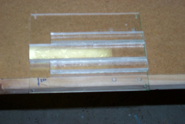 This is the finished base plate. I decided not to paint it since it looks
more interesting as a clear assembly.
Below you can see the finished result.
This is the finished base plate. I decided not to paint it since it looks
more interesting as a clear assembly.
Below you can see the finished result.
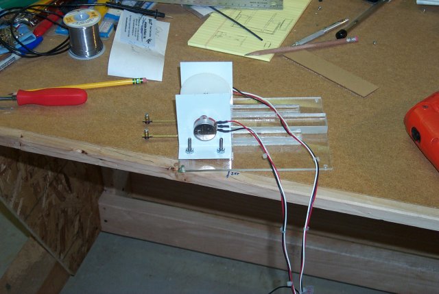 Here is an extreme close-up:
 The pots are high-precision 100K Ohm rotaries. Since they're high-precision
they won't withstand the cycle count that a more robust part could handle,
but they'll last until I can replace them with an equivalent rotary Hall
Effect Device like the ones being used in the Thrustmaster Cougar refit
kits.
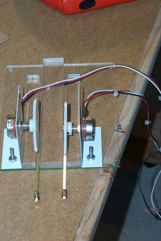
The racks are 1/8" wide brass with Du-Bro pushrod keepers attached to the
ends. It turned out after installation that these keepers were too wide so
they were replaced with a pair of Sullivan clevises that I ground down to
a width of .051".
The metal mounts for the pots are drilled in such a way to allow me to
adjust the tension that the gear exerts upon the rack. It's a trick to get
it adjusted correctly. You'll note that the right gear is at a bit of an
angle. This was corrected.
The installation was fairly painless once the fit & finish issues were
resolved - the racks needed a bit more room cut into the base plate to
prevent jamming on the edge.
The pots are high-precision 100K Ohm rotaries. Since they're high-precision
they won't withstand the cycle count that a more robust part could handle,
but they'll last until I can replace them with an equivalent rotary Hall
Effect Device like the ones being used in the Thrustmaster Cougar refit
kits.
The racks are 1/8" wide brass with Du-Bro pushrod keepers attached to the
ends. It turned out after installation that these keepers were too wide so
they were replaced with a pair of Sullivan clevises that I ground down to
a width of .051".
The metal mounts for the pots are drilled in such a way to allow me to
adjust the tension that the gear exerts upon the rack. It's a trick to get
it adjusted correctly. You'll note that the right gear is at a bit of an
angle. This was corrected.
The installation was fairly painless once the fit & finish issues were
resolved - the racks needed a bit more room cut into the base plate to
prevent jamming on the edge.
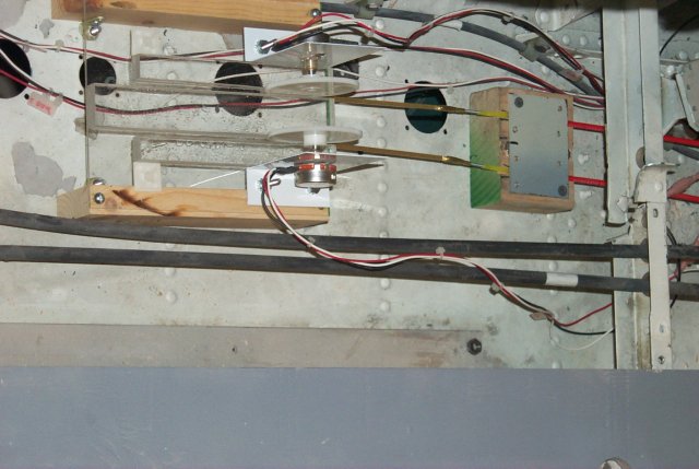 You can see how the pushrods connect to the racks. It's amazing how
applicable model airplane hardware can be in a home-built flight simulator!
You can see how the pushrods connect to the racks. It's amazing how
applicable model airplane hardware can be in a home-built flight simulator!
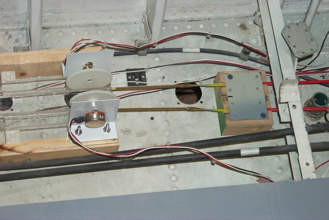 The only thing I'm really not happy with is all the open space between the
pushrod exits and the leading edge of the mounting plate. I don't think the
racks have enough support. I'm hoping it doesn't become an issue in the
future since there is little room to work in there as it is.
The two black tubes that are running along parallel to the throttle
mechanism are the toe brake pushrods. These are the original parts as
installed when the jet was built.
The only thing I'm really not happy with is all the open space between the
pushrod exits and the leading edge of the mounting plate. I don't think the
racks have enough support. I'm hoping it doesn't become an issue in the
future since there is little room to work in there as it is.
The two black tubes that are running along parallel to the throttle
mechanism are the toe brake pushrods. These are the original parts as
installed when the jet was built.
Back to the Tech Index