F-15 Flight Control
System
Part II - Directional Control
By B.P. "PERRY" HOFFMAN/ Senior Engineer. Flight Control Section. Avionics Engineering Laboratories
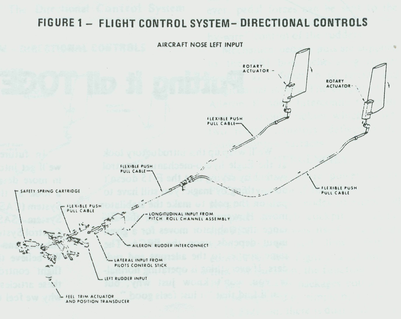
Directional control of the Eagle conies from two vertical tins and two synchronized rudder control surfaces (Figure 1). Conventional rudder pedals position the rudder control surfaces. All rudder pedal inputs go through the Aileron Rudder Interconnect (ARI) box. a part of the Control Stick Boost/ Pitch Compensator. The ARI combines rudder pedal signals with functions of roll and pitch, providing turn coordination over a wide range of pitch and roll maneuvers.
Input authority to the rudder control surfaces in production F-15 aircraft is 15 degrees maximum. Lateral control slick inputs are scheduled within the ARl box for a maximum surface deflection between zero and 30 degrees depending upon longitudinal slick position.
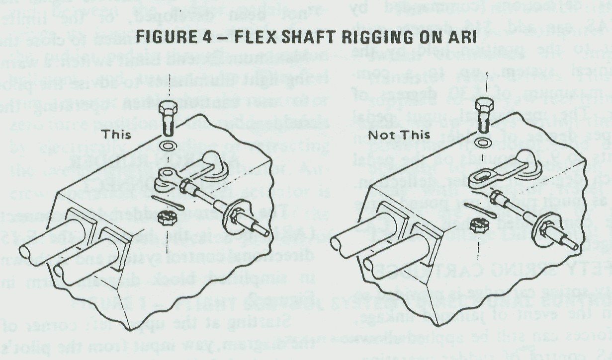
The ARI output is fed via flexible push-pull shafts to each of the rudder control surface actuators. The F-15 rudder power actuator is a part of the rudder hinge, allowing a smooth, streamlined surface with no linkage to wear or jam.
DIRECTIONAL TRIM
The F-15 feel trim actuator, forward and between the rudder pedals, receives its basic position signals from the rudder pedals through a common bellcrank and torque tube. The feel trim actuator establishes the neutral or zero force position of the rudder pedals by electrically extending or retracting the overall length of the actuator. Aircrew operation of the feel actuator is accomplished through actuation of the Yaw Trim switch, located just aft of the right-hand throttle. All trim circuitry is dual so that no single failure can result in runaway trim.
The Yaw Trim switch signal goes to the CAS roll/yaw computer where the switch commands are amplified by transistor relay drivers. This output is supplied to the yaw feel trim actuator, picking up relays within the actuator, powering its motor, and driving the actuator to a new position. Simultaneous with actuator travel, electrical signals are generated by a pair of Linear Voltage Differential Transformers (LVDT). These signals are fed back to the CAS roll/yaw computer and are used for three distinct functions. The signals:
• Establish actuator neutral when the takeoff-trim button is held depressed.
• Limit actuator travel through use
of voltage level detectors within the
CAS roll/yaw computer to prevent
driving the trim actuator into its mechanical stops.
• Advise the yaw CAS of a change
in trim command so that the CAS
doesn't defeat the pilot-inserted trim.
A safety spring cartridge is provided so that, in the event of jammed linkage, pedal forces can still be applied allowing CAS control of rudder operation. This provides an excellent "fly-by-wire" rudder system allowing safe return to the Eagle's nest. This also permits continued use of the nose-wheel steering system with a jammed rudder link. The same applies in the event of a linkage separation: CAS can again supply the pilot pedal commands to the rudder.
A rudder pedal limiter has recently been added to the rudder pedal torque tube. At Mach 1.5 or greater, a discrete signal from the left-hand air inlet controller actuates the pedal limiter actuator, physically restricting movement of the torque tube and pedals thus limiting rudder surface deflection to no more than 5 degrees. This prevents excessive rudder-induced rolls in a flight regime where roll/yaw coupling is a potential hazard. If the right-hand air inlet controller has not attained Mach 1.5 and the discrete signal has not been developed, or the limiter actuator has not extended to close the Maximum Extend Limit switch, a warning light illuminates to advise the pilot to use caution when operating the rudders.
AILERON-RUDDER
INTERCONNECT
The Aileron-Rudder
Interconnect (ARI) box is the heart of the F-15 directional control
system and is shown in simplified block diagram form in Figure 2.
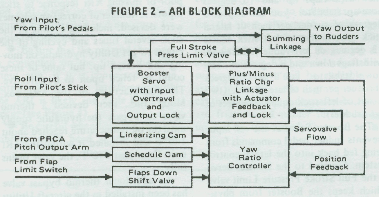
Starting at the upper left corner of the diagram, yaw input from the pilot's pedals is fed directly into a summing linkage and out to the rudders. Since this function is a straight-through linkage arrangement with no hydraulic boost at the output, rudder linkage friction downstream of the ARI can adversely affect the ability of the rudder control surfaces to return to neutral when pedal forces are relaxed. This means that the maintenance man needs to eliminate all possible sources of friction within flex cables and bell-cranks during any maintenance action. Roll input from the pilot's stick and pitch output from the Pitch/Roll Channel Assembly (PRCA) harmonize the rudder output through the Yaw Ratio Controller, the Plus/Minus Ratio Changer linkage, and the summing linkage.
The Flaps Down shift valve
modifies the schedule allowing more rudder, sooner, with flaps down
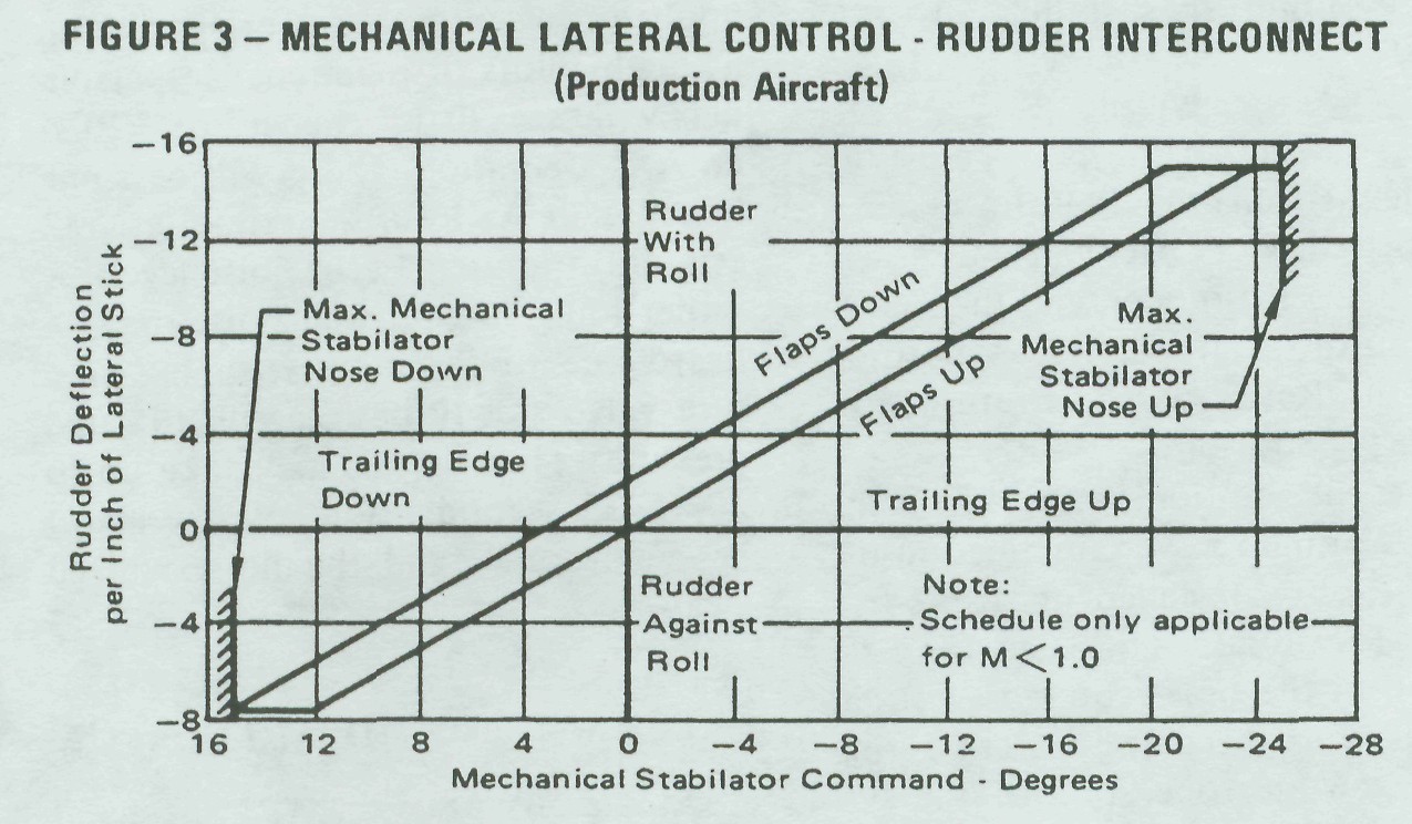
than is available through the flaps up schedule. Looking at the
graph (Figure 3), note that with flaps up
and 10 degrees nose-up stabilator. you can expect 6 degrees of
rudder per inch of lateral stick (two inches of left stick
equals 12 degrees of left rudder). Likewise, with flaps down
and 8 degrees of nose-down stabilator, you'll get 3 degrees
of rudder per inch of lateral stick (two inches of left stick
equals 6 degrees of right rudder).
The Booster Servo at the roll input prevents rudder pedal commands from being fed back into the lateral control system. Coupled to the Booster Servo is the Full Stroke Pressure Limit valve which keeps the Booster from physically overloading the ARI structure as the ram reaches full stroke and simultaneous pedal inputs are applied.

Fig. #3: Mechanical Lateral Control - Rudder Interconnect (Production Aircraft)
Since no ARI functions are required with the aircraft supersonic, a hydraulic shutoff valve located in the PRCA Pitch Ratio Controller turns off the supply pressure to the ARI unit when the aircraft reaches Mach 1. Rudder pedal commands are still available, as are the 15 degree CAS commands.
The Rapid Shutoff valve is actuated by the anti-skid wheel spin-up signal. Since we don't want the rudder to be controlled by lateral stick during cross-wind landings, lateral stick inputs to the rudder are turned off at ground-roll speeds of 50 knots or greater. The maintenance technician can duplicate this during preflights. While holding lateral and longitudinal stick inputs, note the rudder deflections, place the Anti-Skid switch to OFF. and the rudder should rapidly return to the trim position. Reselecting Anti-Skid should return the rudder to its deflected position within 25 to 35 seconds. You can get the same results by turning the Roll or Pitch Ratio switches to EMERGENCY. ARI will shut down, neutralizing the rudder, and the rudder will return to its deflected position when the Ratio switch is returned to the AUTO position.
A recent addition to the ARI is the Rapid Warm-up valve contained in the -17 ARI box installed in all production F-15 aircraft. The need for a reduction in the time required to attain ARI operation became apparent during the first winter operation of the system in St. Louis. On several occasions aborts and near-aborts were blamed on poor or missing ARI response to stick inputs. A number of corrective schemes were devised, including cycling of the stick several times and cycling of the ramps to get Utility hydraulic oil moving and heated up, but none of these could be relied upon to be effective. The manufacturer of the ARI box. Moog, Inc.. then devised a thermo valve to bypass the hydraulic supply until the oil temperature reached about 140°F and installed it within the ARI unit. Once past 140°F, the valve opens fully.
The Booster Servo at the roll input prevents rudder pedal commands from being fed back into the lateral control system. Coupled to the Booster Servo is the Full Stroke Pressure Limit valve which keeps the Booster from physically overloading the ARI structure as the ram reaches full stroke and simultaneous pedal inputs are applied.
Since no ARI functions are required with the aircraft supersonic, a hydraulic shutoff valve located in the PRCA Pitch Ratio Controller turns off the supply pressure to the ARI unit when the aircraft reaches Mach 1. Rudder pedal commands are still available, as are the 15 degree CAS commands.
The Rapid Shutoff valve is actuated by the anti-skid wheel spin-up signal. Since we don't want the rudder to be controlled by lateral stick during cross-wind landings, lateral stick inputs to the rudder are turned off at ground-roll speeds of 50 knots or greater. The maintenance technician can duplicate this during preflights. While holding lateral and longitudinal stick inputs, note the rudder deflections, place the Anti-Skid switch to OFF. and the rudder should rapidly return to the trim position. Reselecting Anti-Skid should return the rudder to its deflected position within 25 to 35 seconds. You can get the same results by turning the Roll or Pitch Ratio switches to EMERGENCY. ARI will shut down, neutralizing the rudder, and the rudder will return to its deflected position when the Ratio switch is returned to the AUTO position.
A recent addition to the ARI is the Rapid Warm-up valve contained in the -17 ARI box installed in all production F-15 aircraft. The need for a reduction in the time required to attain ARI operation became apparent during the first winter operation of the system in St. Louis. On several occasions aborts and near-aborts were blamed on poor or missing ARI response to stick inputs. A number of corrective schemes were devised, including cycling of the stick several times and cycling of the ramps to get Utility hydraulic oil moving and heated up, but none of these could be relied upon to be effective. The manufacturer of the ARI box. Moog, Inc.. then devised a thermo valve to bypass the hydraulic supply until the oil temperature reached about 140°F and installed it within the ARI unit. Once past 140°F, the valve opens fully.