The Hydraulic Systems consist of three independent systems: Power Control 1 (PC-1), Power Control 2 (PC-2), and Utility. PC-1 and PC-2 systems power the primary flight controls and the Utility system supplies all other requirements, plus back-up for stabilator longitudinal and roll control, aileron roll control, and rudder directional control. Hydraulic power is available to adequately and safely maintain control for flight and landing with any one of the three systems operational.
INTERFACE OF SYSTEMS
The block diagram shows the various
subsystems in the "A" and "B" circuitry of the PC-1, PC-2, and
Utility systems. In the Utility system, the "A" circuit lines are
primarily on the left side of the aircraft and the "B" circuit is
primarily on the right-hand side. This improves survivability from a
gunfire standpoint.
Since any one of the three hydraulic
systems can maintain a supply of hydraulic pressure to the control
system, it is obvious, as you refer to the illustration, that the
crisscross of hydraulic supply to the flight controls from left and
right engine driven pumps, through RLS circuitry and switching
valves, gives multiple redundancy of hydraulic supply to the F-15
primary flight control components. Here is what will happen during
several emergency situations:
- When all electrical power is lost,
control is maintained with ailerons
and differential stabilator for roll,
stabilator for pitch, and two rudders.
- When either PC hydraulic system
plus the Utility hydraulic system, and
all electrical power are lost, control is
maintained with ailerons on one wing
and differential stabilator for roll, stabilator
for pitch, and one rudder. (If PC-2 and Utility are lost, the Control Stick Boost and Pitch Compensator will be inoperative.)
- When all mechanical controls are
lost, control is maintained by the
Control Augmentation System driving
the differential stabilator for roll and
pitch, and both rudders.
- When both PC-1 and PC-2 hydraulics are lost, control is maintained with the Utility hydraulic system supplying power to all primary flight controls.
HYDRAULIC PUMP
For ease of maintenance, the F-15 pump
was designed as a plug-in type. The intake, outlet, and case drain
fluid flows are directed to the spline-drive end of the pump where
they pass through quick disconnect couplings. These connect the pump
to an aircraft mounted manifold which has rigid tubing attached,
allowing the pumps to be installed and removed without disconnecting
hoses and tubes. Doing away with hoses eliminates the possibility of
chafing and there are fewer leakage points. Self-sealing checks were
incorporated to prevent line drainage during replacement. The pump
also incorporates fast-response compensator shutoff to lower
hydraulic system pressure spikes. Basic system accumulators found in
most aircraft have been eliminated (these are high replacement items
and can be responsible for introducing air into a hydraulic system).
FILTER PACKAGE
Each of the three systems (PC-1, PC-2,
and Utility) has a single filter module which incorporates pressure
and return filters, system relief valves, pressure switches,
pressure transmitters, and pump outlet check valves. As a result,
there is one module and one door per system, simplifying servicing.
All pressure and return elements are non-collapsible at 4500
PSI ΔP and are in one size and type (15 micron absolute with an
approximate 8 gram dirt capacity) for commonality and good logistics
control. The filters have self-sealing checks incorporated to prevent line drainage, and there are
delta-P indicators at the bottom of the bowl to reveal a dirty
element. The bowls must be removed to reset the indicator and the
bowl cannot be replaced without an element inside. The bowls feature
self-locking ratchets, and are non-interchangeable
pressure-to-return to assure murphy-proof maintenance. The relief
valve is a fast-response type backing up the fast-response pump
compensator allowing elimination of accumulators. The pressure
filter is non-bypass while the return filters are dual purpose. They
filter the system return oil (bypass) and the pump case drain
(non-bypass). This allows the pump case drain (which carries
particles from the hardest-working most wear-producing component in
the system) to have a large, high-dirt capacity filter with no
danger of particle recirculation to accelerate pump wear. This also
prevents wear particles from a failing Utility pump from
contaminating the second Utility system pump.
RESERVOIRS
Each of the three F-15 bootstrap type
reservoirs incorporates reservoir level sensing (RLS). RLS works on
the principle that a leak developed in the aircraft will cause the
reservoir level to sink. As the level decreases, RLS sensing
mechanically operates a valve which shuts off half the system
(designated "A"). If this stops the leak, the reservoir level will
stop sinking and the other half of the system (designated "B") will
be retained.
On the other hand, if the leak
•continues, the reservoir will continue to deplete until a second
valve shuts off the "B" half of the system. When "B" shuts off, the
"A" system returns, reactivating one-half of the system. This is
accomplished by mechanical linkage between the "A" and "B" shutoff
valves. Leaks in the pump or filter circuit are not protected by
reservoir level sensing. However, as you can see, RLS improves the
survivability of the aircraft.
The gaging system on the F-15 reservoirs
is also unique as the gaging is temperature compensating to allow
for volume increase or decrease due to oil temperature changes. Automatic overflow occurs
if the reservoir is overfilled, preventing reservoir damage.
SWITCHING VALVES
Another new type of
hydraulic component found in the F-15 is a "switching valve." Four
of these are used to further improve the survivabil-ity of the
primary flight control systems. Two switching valves are in the aileron circuit;
two others are in the tandem stabilator/rudder circuits.
These valves allow
the normal operating pressure from the "B" RLS circuits of both
PC-1 and PC-2 to pass directly through the switching valves to
the left and right ailerons, to one side of each tandem
stabilator, and to each rudder. Should a "B" circuit lose
pressure for any reason (leak, pump failure, etc.), the switching valves will move to a test
position to assure that the system downstream of the switching valve
is intact. If system integrity is verified, the Utility system will
be switched into the downstream flight control actuators. This test
position prevents loss of Utility oil should the break be downstream
of the valve.
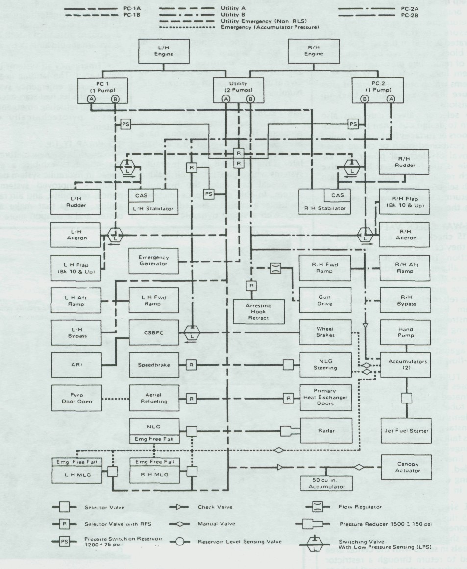 F-15 Hydraulic System Diagram