January 01, 2004
One of the most important things in this project is how I distribute power
to the devices that need it. The simulator will use both AC and DC power
systems, but since the DC power supplies require AC to run, the AC power
system will be installed first.
As you might have seen earlier, there are two IEC power connectors mounted
on one of the new panels that are installed in the new nose section.
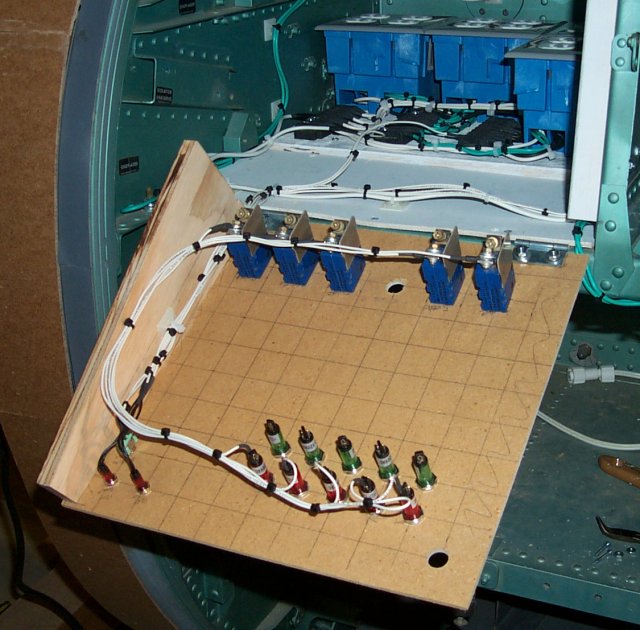
They're there to deliver AC power to this:
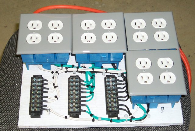 The AC outlets are there to supply power to any low-power Wall Wart type
power supplies that devices like the USB EPIC need. The terminal strips
allow a direct connection to the DC power supplies. The connector board
is split into two circuits of 15A each as supplied by the two IEC
connectors on the front of the sim. The AC BUS on the terminal blocks is
split into two as well. The "upper" four are Bus #1 and the lower are Bus
#2. The grounds are common to both.
Here's how it looked as the installation procedure began:
The AC outlets are there to supply power to any low-power Wall Wart type
power supplies that devices like the USB EPIC need. The terminal strips
allow a direct connection to the DC power supplies. The connector board
is split into two circuits of 15A each as supplied by the two IEC
connectors on the front of the sim. The AC BUS on the terminal blocks is
split into two as well. The "upper" four are Bus #1 and the lower are Bus
#2. The grounds are common to both.
Here's how it looked as the installation procedure began:
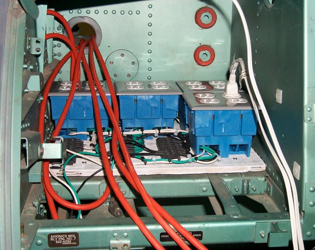 It was at this point that I started thinking about power system problems
and how bad would it get if it really went bad?
I stopped working on the AC system for a week or so while I worked out a
safer way to bring power to the simulator. That is one of the reasons the
Instructor Station was developed.
I decided that for safety's sake, I was going to install monitor
indicators in all sections of the power system as well as circuit breakers
for both the AC and DC power systems.
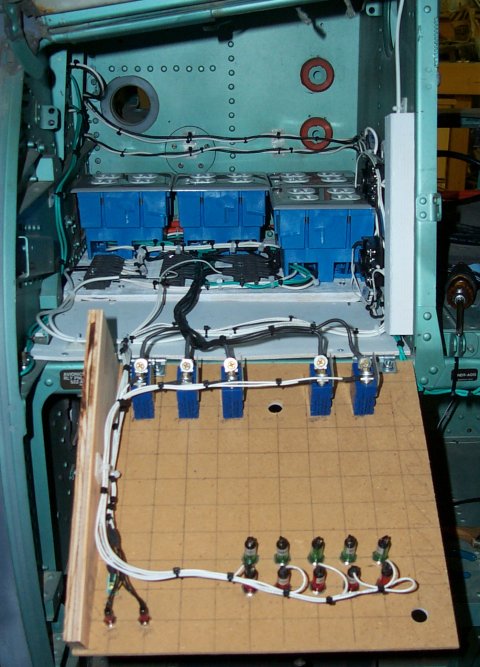
One of the benefits of this new design was a much neater installation:
It was at this point that I started thinking about power system problems
and how bad would it get if it really went bad?
I stopped working on the AC system for a week or so while I worked out a
safer way to bring power to the simulator. That is one of the reasons the
Instructor Station was developed.
I decided that for safety's sake, I was going to install monitor
indicators in all sections of the power system as well as circuit breakers
for both the AC and DC power systems.
One of the benefits of this new design was a much neater installation:
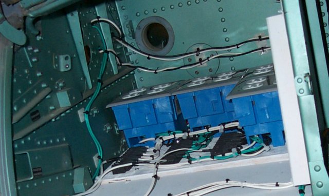 This photo was originally taken in November and some changes have been
made since then, but this still shows how it's going together.
Here's a few pics of the AC Monitor panel as it goes together:
This photo was originally taken in November and some changes have been
made since then, but this still shows how it's going together.
Here's a few pics of the AC Monitor panel as it goes together:
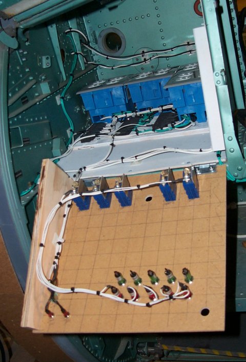 The blue devices are aircraft circuit breakers. They're nice and small
and use a 9/16" mounting hole like a standard toggle switch does. This
comes in handy when you're drilling a lot of them.
The blue devices are aircraft circuit breakers. They're nice and small
and use a 9/16" mounting hole like a standard toggle switch does. This
comes in handy when you're drilling a lot of them.
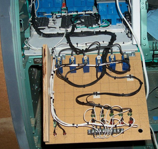
 Here is a shot of the panel about 75% complete:
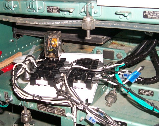
 One thing of note here are the two 48V Relay sockets. They're somewhat
hard to see, but they're attached to the bulkhead on the right. They
control all the AC power that comes into the simulator. They're activated
by switches on the Instructor Station. No station, no power.
Here's a better picture of the relay sockets:
One thing of note here are the two 48V Relay sockets. They're somewhat
hard to see, but they're attached to the bulkhead on the right. They
control all the AC power that comes into the simulator. They're activated
by switches on the Instructor Station. No station, no power.
Here's a better picture of the relay sockets:
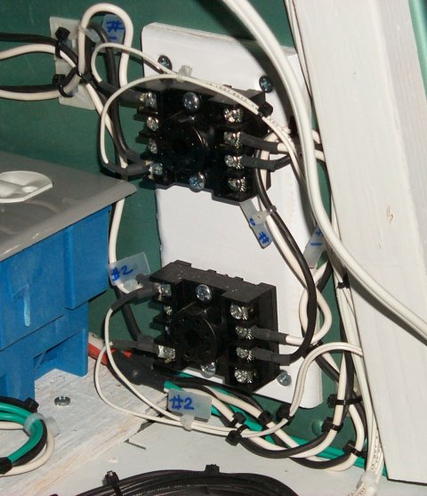 The control wiring hasn't been installed for these yet.
This is actually a pretty good safety feature. If the main control cable
from the console isn't connected to the simulator, there's no way that AC
power can be turned on in the simulator, making it safer to work on.
....and completed! (For the most part)
The control wiring hasn't been installed for these yet.
This is actually a pretty good safety feature. If the main control cable
from the console isn't connected to the simulator, there's no way that AC
power can be turned on in the simulator, making it safer to work on.
....and completed! (For the most part)
 The monitor panel is designed to tell me at a glance if power is going
where it should (and if need be, where it shouldn't!).
The tiny toggle switch is used to turn on the rope lighting I'm using to
illuminate the avionics bay while I'm working in there. It actually works
pretty well!
The two small red lamps in the upper left corner of the panel are for
incoming AC power. They're connected to the input side of the main AC
relays. If they're on it means the simulator is hot and it's a dumb idea
to go sticking your hands in the area behind the monitor panel.
Once the simulator has been plugged in (thus lighting the two small pilot
lamps), the AC mains relays can be activated from the Instructor Station.
Doing this energizes both Bus #1 and #2, illuminating the 5 red indicators
at the top of the panel. The 5 red lamps are wired after the circuit
breakers so if one of the breakers is popped or non-visibly failed, the
lamp will remain dark. No light, no power, problem!
At this point, the DC power systems can be activated from the Instructor
Station. There are 3 24VDC power supplies and 2 5VDC supplies. As the
operator flips the switches on the IS, the green lamps on the monitor
panel will illuminate. This tells me that AC power is going to the DC
power supply that the lamp represents. The DC power supplies are
controlled by a bank of 5 48V relays that are installed on the right side
avionics bay.
Here's a shot of the relay board with a single relay sitting atop it:
The monitor panel is designed to tell me at a glance if power is going
where it should (and if need be, where it shouldn't!).
The tiny toggle switch is used to turn on the rope lighting I'm using to
illuminate the avionics bay while I'm working in there. It actually works
pretty well!
The two small red lamps in the upper left corner of the panel are for
incoming AC power. They're connected to the input side of the main AC
relays. If they're on it means the simulator is hot and it's a dumb idea
to go sticking your hands in the area behind the monitor panel.
Once the simulator has been plugged in (thus lighting the two small pilot
lamps), the AC mains relays can be activated from the Instructor Station.
Doing this energizes both Bus #1 and #2, illuminating the 5 red indicators
at the top of the panel. The 5 red lamps are wired after the circuit
breakers so if one of the breakers is popped or non-visibly failed, the
lamp will remain dark. No light, no power, problem!
At this point, the DC power systems can be activated from the Instructor
Station. There are 3 24VDC power supplies and 2 5VDC supplies. As the
operator flips the switches on the IS, the green lamps on the monitor
panel will illuminate. This tells me that AC power is going to the DC
power supply that the lamp represents. The DC power supplies are
controlled by a bank of 5 48V relays that are installed on the right side
avionics bay.
Here's a shot of the relay board with a single relay sitting atop it:
 This board is out of position because I was working on it. It's normally
installed in the tray mount to the right. It's marked "APML ELEK CONT".
You'll notice there are 6 relay sockets. The 6th relay is energized from
the IS and it in turn supplies AC power to the 48VDC power supply that the
other relays depend upon.
Here is a pic of the power supplies in their current configuration:
This board is out of position because I was working on it. It's normally
installed in the tray mount to the right. It's marked "APML ELEK CONT".
You'll notice there are 6 relay sockets. The 6th relay is energized from
the IS and it in turn supplies AC power to the 48VDC power supply that the
other relays depend upon.
Here is a pic of the power supplies in their current configuration:
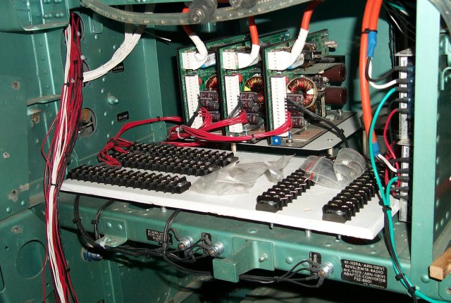 Left to right, you see the 3 24VDC supplies and to the far right are the
two 5VDC supplies. The DC supplies all utilize a common ground by
connecting to the original ground lugs that are present in the avionics
bays. The AC grounds also attach to the frame as well.
Another feature that will be part of the IS is pilot lamps that indicate
that the DC power supplies are functioning. Look for these when I update
the Instructor Station page in the future.
Left to right, you see the 3 24VDC supplies and to the far right are the
two 5VDC supplies. The DC supplies all utilize a common ground by
connecting to the original ground lugs that are present in the avionics
bays. The AC grounds also attach to the frame as well.
Another feature that will be part of the IS is pilot lamps that indicate
that the DC power supplies are functioning. Look for these when I update
the Instructor Station page in the future.
Back to the Tech Index