April 13th, 2003
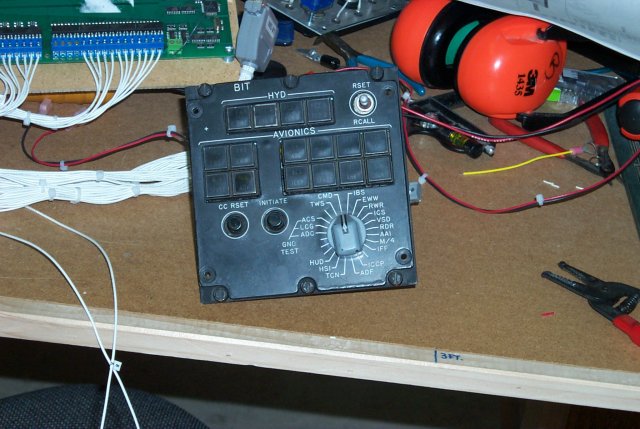 This is the BIT panel for the F-15. The panel I'm using is a pre-MSIP1 example.
The primary difference between pre and post MSIP BIT panels is the two dual
indicator lamps that are missing in the second row and third rows.
The BIT panel is utilized by ground and flight crew to test the various
major subsystems in the F-15C. The tests are split into two major categories,
Hydraulics and Avionics. By selecting the required test with the rotary knob
and then pressing the "Initiate" button, the onboard computer will run the
selected system through it's default operation tests.
In the event of an onboard systems failure, the relevant lamp on the BIT panel
will illuminate along with the corresponding indicator on the Master Caution Panel.
To use the real F-15 BIT panel in my simulator, I had to totally remove all the
old wiring and completely replace it. The image below shows the marked difference
between the original and rebuilt panels.
This is the BIT panel for the F-15. The panel I'm using is a pre-MSIP1 example.
The primary difference between pre and post MSIP BIT panels is the two dual
indicator lamps that are missing in the second row and third rows.
The BIT panel is utilized by ground and flight crew to test the various
major subsystems in the F-15C. The tests are split into two major categories,
Hydraulics and Avionics. By selecting the required test with the rotary knob
and then pressing the "Initiate" button, the onboard computer will run the
selected system through it's default operation tests.
In the event of an onboard systems failure, the relevant lamp on the BIT panel
will illuminate along with the corresponding indicator on the Master Caution Panel.
To use the real F-15 BIT panel in my simulator, I had to totally remove all the
old wiring and completely replace it. The image below shows the marked difference
between the original and rebuilt panels.
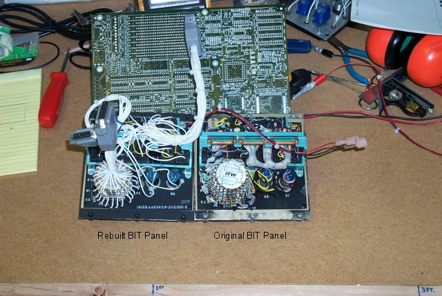 As you can see, it was quite a job. The end result was worth the work though.
Because of how much the BIT panel does, it took a whole 0/32/32 Phidget to
use it. Therefore, I decided to mount the 0/32/32 Phidget close to the panel
and use a USB hub to connect it to the main computer.
As you can see, it was quite a job. The end result was worth the work though.
Because of how much the BIT panel does, it took a whole 0/32/32 Phidget to
use it. Therefore, I decided to mount the 0/32/32 Phidget close to the panel
and use a USB hub to connect it to the main computer.
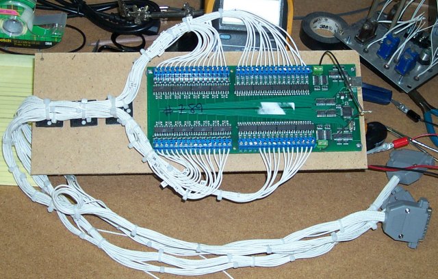 This is what the subassembly looks like. Pretty busy eh? The BIT panel consumes
all 32 outputs and 28 of the 32 available inputs. It will be installed right
underneath the panel in the left side console. The lamps are powered by
the Phidget and are 28VDC operating at 24VDC.
1 Multi Stage Improvement Program
This is what the subassembly looks like. Pretty busy eh? The BIT panel consumes
all 32 outputs and 28 of the 32 available inputs. It will be installed right
underneath the panel in the left side console. The lamps are powered by
the Phidget and are 28VDC operating at 24VDC.
1 Multi Stage Improvement Program
Back to the Tech Index