January 01, 2004
One important part of the simulator has been missing up until this point.
The Instructor Station. All commercial flight simulators have these and
they're designed to allow full control of the simulator without disturbing
the user. Typically, an Instructor Station is used to configure the
simulator for the airport and environment the student will be flying in.
It's also used to create in-flight emergencies for training purposes.
Many also include basic controls such as simulator power which is why I'm
getting started on this right now.
As part of the AC and DC power system design for the simulator, I had
originally planned to place the power system controls in the forward
avionics bay. The problem with this is that to turn the simulator on or
off, you'd have to pop the three latches that hold the avionics door
closed, lift it over your head and then lock it in place before you could
even reach the controls.
Instead, I decided to create a roll-around console that could not only be
a place where the power system controls could be located, but a computer
could be installed in it so it could be used as an Instructor Station as
well.
Here's the beginnings of that project:
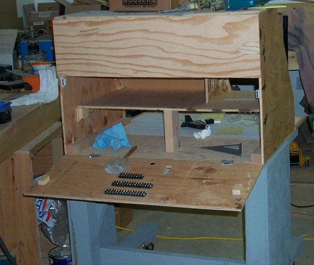
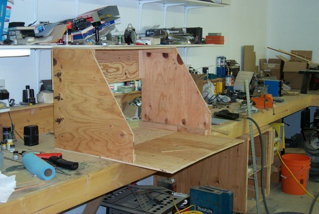 You can see that it's a fairly simple box. The console is 4' wide and 3'
high. There's plenty of space in there for whatever I need to put in it.
You can see that it's a fairly simple box. The console is 4' wide and 3'
high. There's plenty of space in there for whatever I need to put in it.
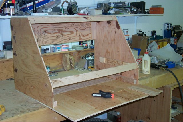 This shows the lower panel support bar in place. It's just a 2x4 that I
ripped down with the table saw. I made a small angle template so I could
match the cut angle of the table saw blade to the angle of the console
sides.
This shows the lower panel support bar in place. It's just a 2x4 that I
ripped down with the table saw. I made a small angle template so I could
match the cut angle of the table saw blade to the angle of the console
sides.
 Here's a different view of the same construction stage. The upper and
lower mounting rails will have metal inserts installed that will allow me
to use 8x32 machine screws to hold the panels in place. The benefit is I
won't be tearing up the wood when I remove and re-install the panels.
Insert and remove a wood screw into pine enough times and you end up with
a ragged hole that has lost so much material that the screw can't find
purchase any longer.
Here's a different view of the same construction stage. The upper and
lower mounting rails will have metal inserts installed that will allow me
to use 8x32 machine screws to hold the panels in place. The benefit is I
won't be tearing up the wood when I remove and re-install the panels.
Insert and remove a wood screw into pine enough times and you end up with
a ragged hole that has lost so much material that the screw can't find
purchase any longer.
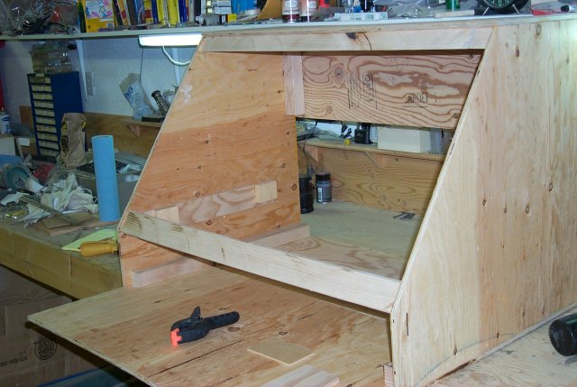
 Here you can see the two panels that will make up the console. The left
panel is narrower because it will only hold power controls and the jacks
for the Instructor Station to Simulator comms link.
Here you can see the two panels that will make up the console. The left
panel is narrower because it will only hold power controls and the jacks
for the Instructor Station to Simulator comms link.
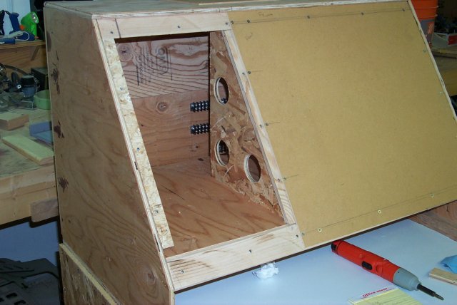 This view shows the power panel removed. The back of the console is
hinged at the bottom and drops down for easy access. The two visible
terminal blocks are for the 39 conductor cable that will connect the
Instructor Station to the simulator. More on this later.
This view shows the power panel removed. The back of the console is
hinged at the bottom and drops down for easy access. The two visible
terminal blocks are for the 39 conductor cable that will connect the
Instructor Station to the simulator. More on this later.
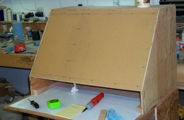
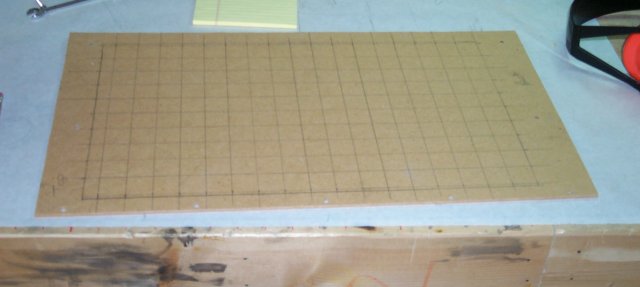 I placed a 1" grid of lines on the back of both the console panels. This
allows me to get the surface painted without having to install any
components in it. Using the grid, I can correctly locate any future
additions to the panel with respect to their alignment to existing parts.
This is what the drop down panel looks like:
I placed a 1" grid of lines on the back of both the console panels. This
allows me to get the surface painted without having to install any
components in it. Using the grid, I can correctly locate any future
additions to the panel with respect to their alignment to existing parts.
This is what the drop down panel looks like:
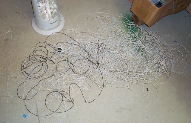
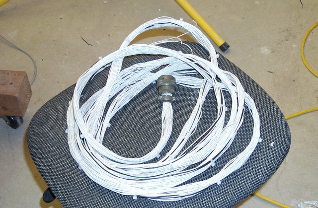
 I'm working on installing the main cable that will run from here to the
simulator. The cable itself is a 39 conductor monstrosity that took 702
feet of wire to construct.
The good part is that it went from this:
I'm working on installing the main cable that will run from here to the
simulator. The cable itself is a 39 conductor monstrosity that took 702
feet of wire to construct.
The good part is that it went from this:
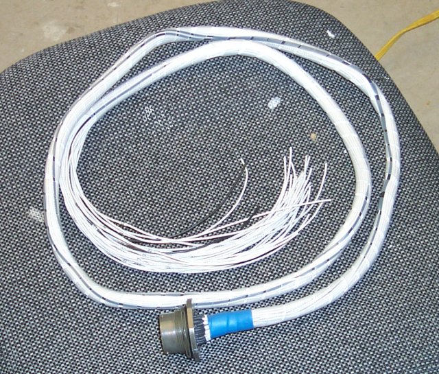
 To this:
 ...fairly quickly.
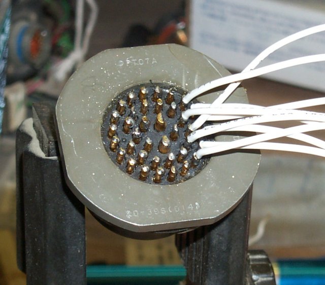
Soldering up this cable wasn't easy and there were two to build. One long
one for the Instructor Console side, and a smaller one for the simulator
end.
Here's the start of the soldering job:
...fairly quickly.
Soldering up this cable wasn't easy and there were two to build. One long
one for the Instructor Console side, and a smaller one for the simulator
end.
Here's the start of the soldering job:
 ...and the finish:
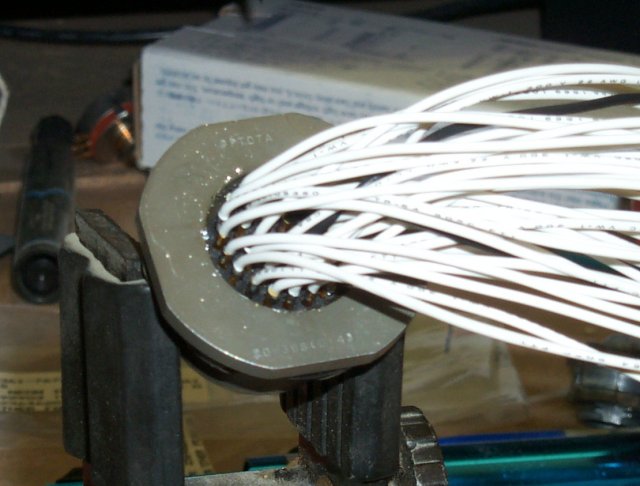
 The whole process took about 3 hours for the longer cable, and about 2 for
the shorter.
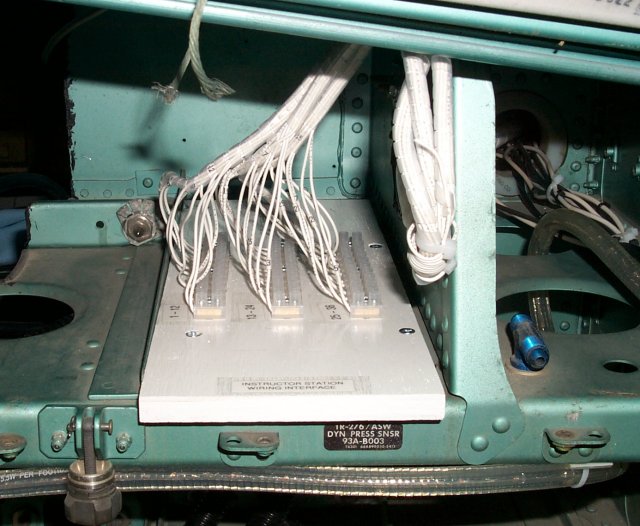
The simulator end of the cable goes into a European style terminal block
board that will distribute the signals to the rest of the simulator:
The whole process took about 3 hours for the longer cable, and about 2 for
the shorter.
The simulator end of the cable goes into a European style terminal block
board that will distribute the signals to the rest of the simulator:
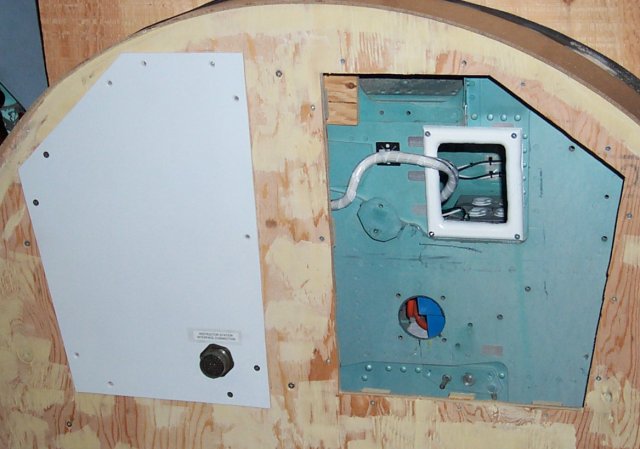
 With this installed, I can finally install the control wiring for the AC
and DC power system relays so those systems can be fully tested.
Here's what it looks from the front with the new connector installed:
With this installed, I can finally install the control wiring for the AC
and DC power system relays so those systems can be fully tested.
Here's what it looks from the front with the new connector installed:
Back to the Tech Index