September 15, 2002
It was with great joy that I recieved my MPCD panel from Desktop Sims.
Unfortunately, it would be a few weeks before any joy returned to the cockpit.
The MPCD panel is in *very* good physical shape considering its age - 15 years.
This thing is so old, the serial number is *7* and it had electrically given
up the ghost. 15 years of life in a part/task trainer, being pounded on by
countless wannabe stick actuators had taken its toll. Only a lot of TLC was
going to keep this poor thing from becoming a bit of framed artwork.
I found that there was some broken wires at the surface of the PCB and they
were hiddn under a pile of RTV. Must Disassemble! *Evil Laugh*
 Upon disassembly, I found that the the circuit board that I was expecting
wasn't. It was two PCBs laminated together. Now normally, this would be no
big deal, but to replace the bad connector, I had to get to the inside face
of the button PCB. After a LOT of words taken from the Most Frequently Used
Profanity list were uttered, I began the delicate process of delaminating the
boards.
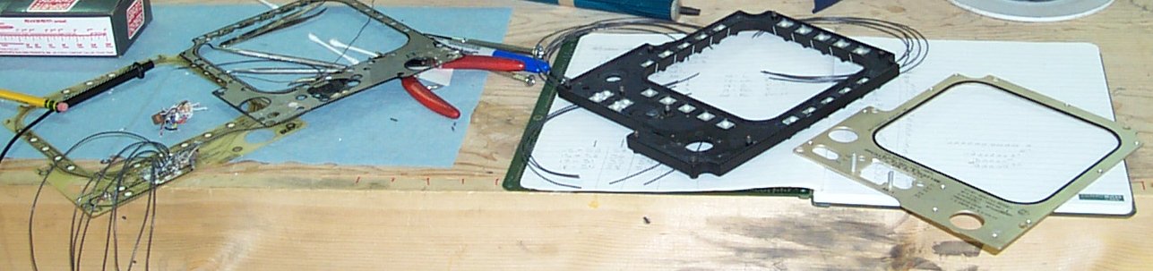
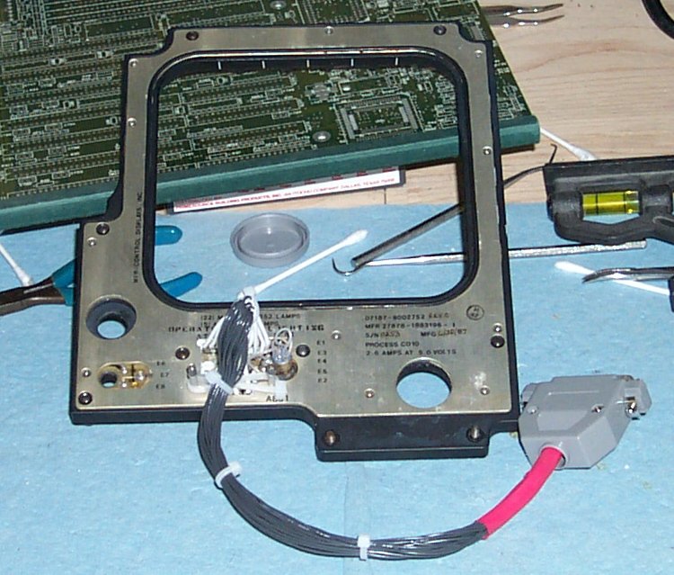
In the image above, you can see the four primary parts of the panel. On the
left is the button PCB and the lighting PCB. On the left is the MPCD light-
plate face and the aluminum backing plate.
The first thing I wanted to do since I'd split them anyway is to make sure
that the bulbs for the lighting illuminated properly and none were damaged.
Upon disassembly, I found that the the circuit board that I was expecting
wasn't. It was two PCBs laminated together. Now normally, this would be no
big deal, but to replace the bad connector, I had to get to the inside face
of the button PCB. After a LOT of words taken from the Most Frequently Used
Profanity list were uttered, I began the delicate process of delaminating the
boards.
In the image above, you can see the four primary parts of the panel. On the
left is the button PCB and the lighting PCB. On the left is the MPCD light-
plate face and the aluminum backing plate.
The first thing I wanted to do since I'd split them anyway is to make sure
that the bulbs for the lighting illuminated properly and none were damaged.
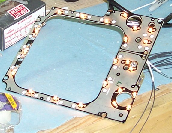 There are 5 lamps across the top (for the L, LC, C, RC and R buttons) that
are not illuminated - they require 28VDC and I tested those before I took this
photo. The other lamps are standard 5VDC grain of wheat bulbs. According
to the information silk-screened onto the back of the panel, all these will
consume 2.6A when lit. If only white LEDs were cheap enough to use as
replacements...
There are 5 lamps across the top (for the L, LC, C, RC and R buttons) that
are not illuminated - they require 28VDC and I tested those before I took this
photo. The other lamps are standard 5VDC grain of wheat bulbs. According
to the information silk-screened onto the back of the panel, all these will
consume 2.6A when lit. If only white LEDs were cheap enough to use as
replacements...
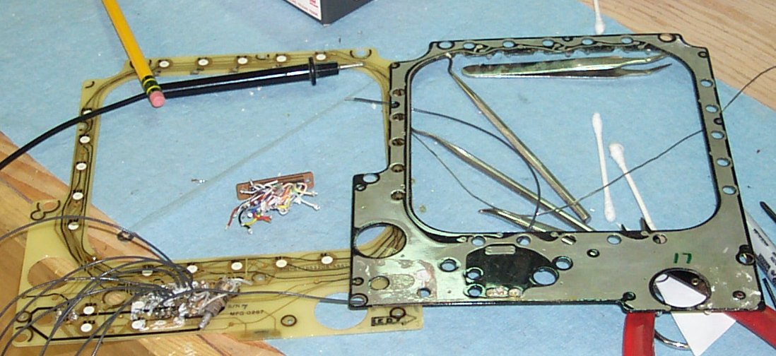 This shows the two PCBs close up and personal. The button PCB is on the left
and the lighting PCB is on the right.
To allow the boards to be re-laminated, the solder "dome" on the inside
surface of the PCB couldn't be more than 1/32nd" high. I'm really glad that
Weller makes a nice and small soldering iron tip. :)
This shows the two PCBs close up and personal. The button PCB is on the left
and the lighting PCB is on the right.
To allow the boards to be re-laminated, the solder "dome" on the inside
surface of the PCB couldn't be more than 1/32nd" high. I'm really glad that
Weller makes a nice and small soldering iron tip. :)
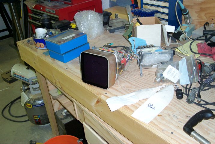
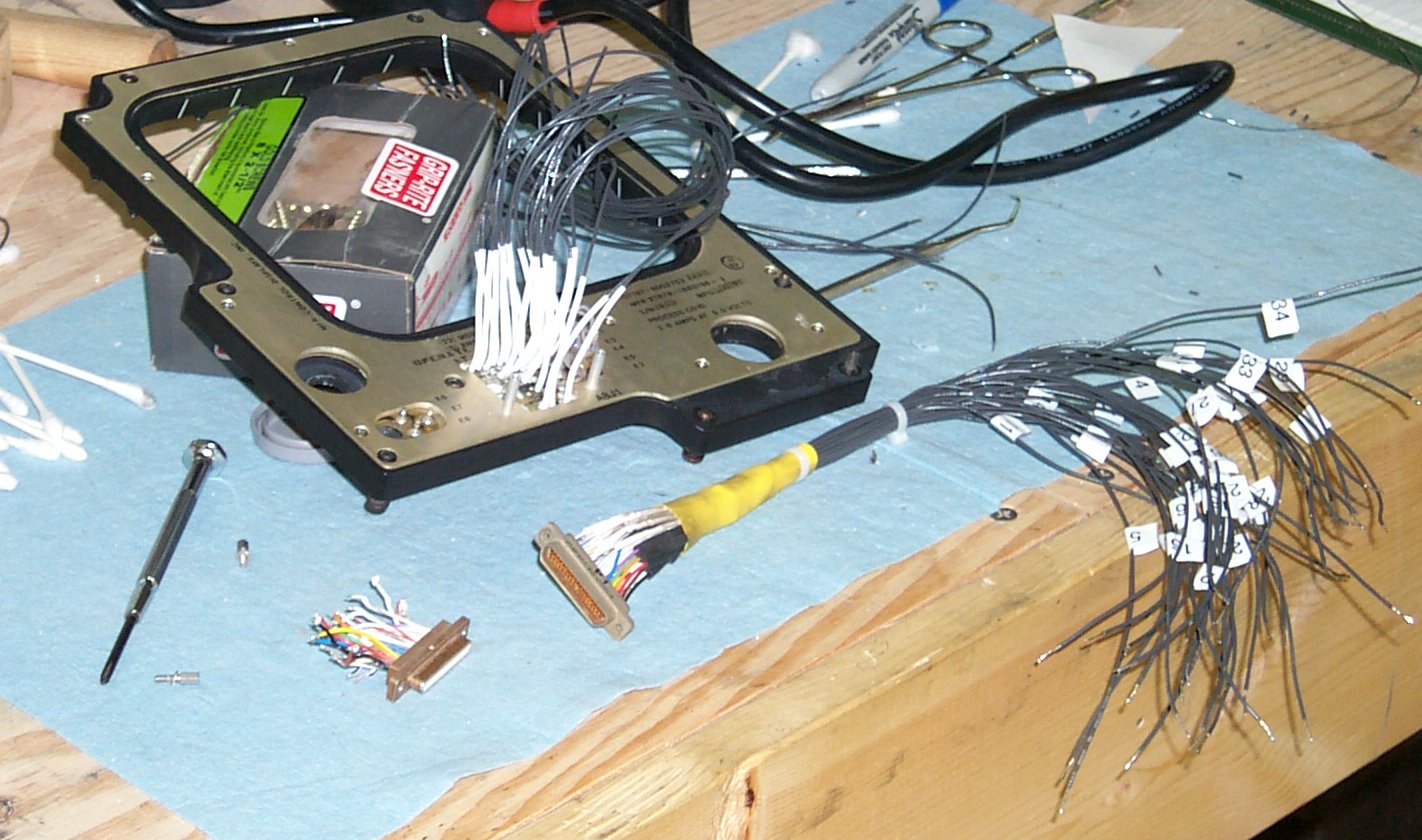 This is the end result of about 6 hours of work. The connector and cable
shown is the original parts. I added some lead to the mating connector
so that I could diagnose the board and find out the wiring matrix. It
was almost wasted effort since I had to replace the connector it mated to
in the end.
This is the end result of about 6 hours of work. The connector and cable
shown is the original parts. I added some lead to the mating connector
so that I could diagnose the board and find out the wiring matrix. It
was almost wasted effort since I had to replace the connector it mated to
in the end.
 This is what the new cable assembly looks like. I've settled on using D-shell
connectors throught the project. They're cheap and since I use crimp pins
that are also soldered on, I'm sure of a good connection. This also allows
me to only use the number of pins that I need for a connection without having
to fight with the tiny solder pots that are found on solder-only D shell
connectors. I buy them in volume from Mouser Electronics for a good price.
The wire used in this harness is 24GA. This was a requirement due to the
tiny size of the plated holes in the PCB that I needed to use. The mating
wiring harness uses the same 22GA wire I use throughout the simulator.
This is what the new cable assembly looks like. I've settled on using D-shell
connectors throught the project. They're cheap and since I use crimp pins
that are also soldered on, I'm sure of a good connection. This also allows
me to only use the number of pins that I need for a connection without having
to fight with the tiny solder pots that are found on solder-only D shell
connectors. I buy them in volume from Mouser Electronics for a good price.
The wire used in this harness is 24GA. This was a requirement due to the
tiny size of the plated holes in the PCB that I needed to use. The mating
wiring harness uses the same 22GA wire I use throughout the simulator.
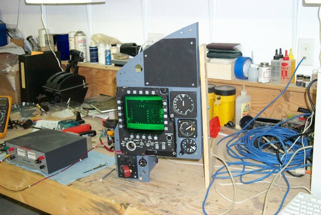
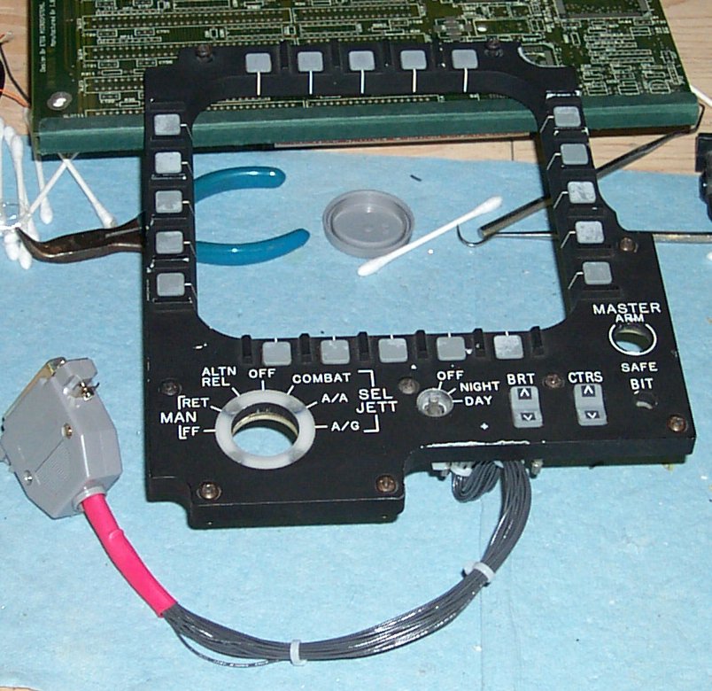 Here's the panel as it looks from the front. It still has a few scars, but
they do more to add character to the panel than they do to detract from its
appearance.
Here's the panel as it looks from the front. It still has a few scars, but
they do more to add character to the panel than they do to detract from its
appearance.
 This is the 7" monochrome VGA display that I'm going to be using for the MPCD
display. This really should be a color CRT, but there are no display
manufacturers that are willing to build a 7" color display for ANY amount
of money. The tubes are just not available. It's frustrating to say the
least.
I had to modify all four of the CRT mounting ears as well as re-arrange how
the PCB fit behind the tube. The tube assembly is mounted on a .75" MDF
support frame that also holds the MPCD button collar. This is definately
NOT what the MACAIR engineers had originally envisioned for this installation. :)
The real MPCD unit was a self-contained, slide-in assembly. Unfortunately, due to the
size of the CRT I have to use, my version has to be built directly on the
instrument panel itself.
This is the 7" monochrome VGA display that I'm going to be using for the MPCD
display. This really should be a color CRT, but there are no display
manufacturers that are willing to build a 7" color display for ANY amount
of money. The tubes are just not available. It's frustrating to say the
least.
I had to modify all four of the CRT mounting ears as well as re-arrange how
the PCB fit behind the tube. The tube assembly is mounted on a .75" MDF
support frame that also holds the MPCD button collar. This is definately
NOT what the MACAIR engineers had originally envisioned for this installation. :)
The real MPCD unit was a self-contained, slide-in assembly. Unfortunately, due to the
size of the CRT I have to use, my version has to be built directly on the
instrument panel itself.
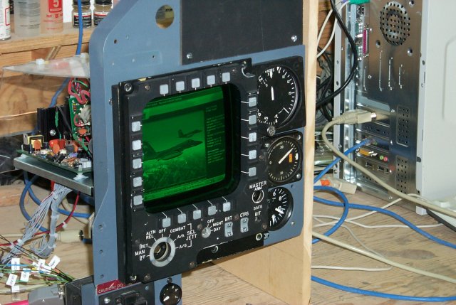
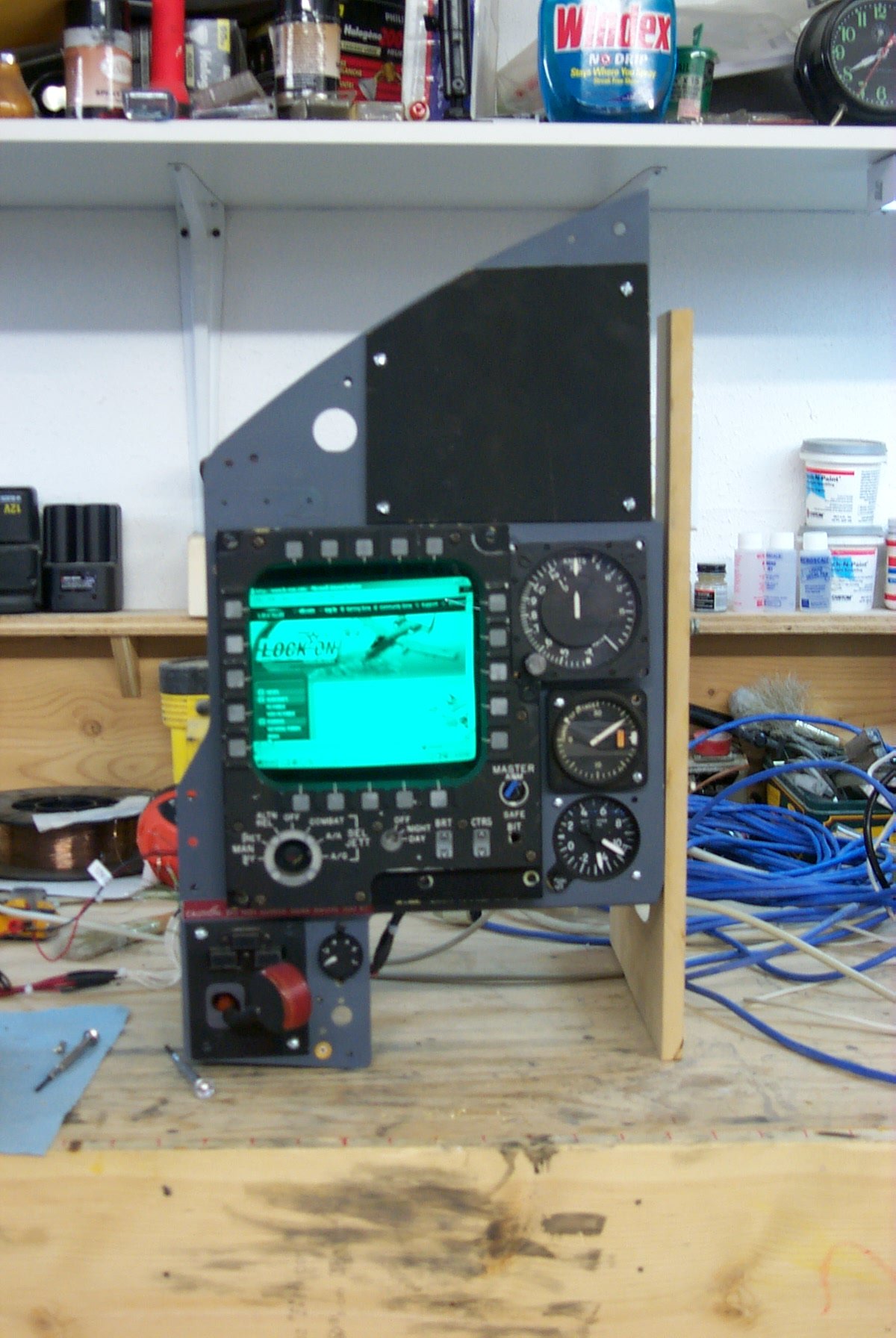
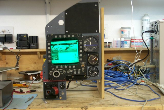
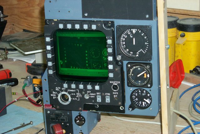 Here is the MPCD mostly assembled. The parts missing are the munitions jettison
selector, the master arm switch and the BIT light.
The display currently shown is a screen shot from the upcoming air combat simulator,
Lock On: Modern Air Combat. The image shown is
the game version of this same instrument panel section. I couldn't resist. *g*
Here's another shot of the panel showing the F-15C reference page from the LO-MAC website:
Here is the MPCD mostly assembled. The parts missing are the munitions jettison
selector, the master arm switch and the BIT light.
The display currently shown is a screen shot from the upcoming air combat simulator,
Lock On: Modern Air Combat. The image shown is
the game version of this same instrument panel section. I couldn't resist. *g*
Here's another shot of the panel showing the F-15C reference page from the LO-MAC website:
 There was a huge problem with the test-out that was performed on the button collar when
I finished rebuilding it. After programming the Hagstrom LP24
keyboard encoder for the matrix that the MPCD button collar used, I was dismayed to find
out that none of it worked correctly. I was concerned that the rework I had done on the
PCB had left a solder bridge or something that was shorting the matrix. I checked the
cable, and sure enough there was a short in the 50 pin IDC connector that I was using to
connect to the LP24. After a quick tear-down and rebuild of the LP24 end of the cable,
everything worked fine.
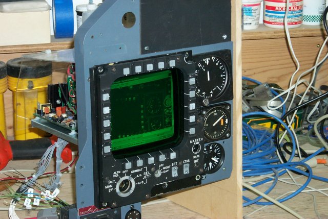
Here are some other shots of the panel displaying various parts of the LO-MAC website:
There was a huge problem with the test-out that was performed on the button collar when
I finished rebuilding it. After programming the Hagstrom LP24
keyboard encoder for the matrix that the MPCD button collar used, I was dismayed to find
out that none of it worked correctly. I was concerned that the rework I had done on the
PCB had left a solder bridge or something that was shorting the matrix. I checked the
cable, and sure enough there was a short in the 50 pin IDC connector that I was using to
connect to the LP24. After a quick tear-down and rebuild of the LP24 end of the cable,
everything worked fine.
Here are some other shots of the panel displaying various parts of the LO-MAC website:
Back to the Tech Index