January 19th, 2002
Well, the SFS box & flight grip is finally ready for installation into the
simulator.
Below is the start of the final wiring process:
 The construction of the SFS box is very simple. I used 1/2" plywood
throughout. The SFS box shape is actually what is found in the E model
of the F-15 and I'm using it here because I was only able to obtain
dimensions for the E version. If I ever get the needed info for the C model
SFS box, I'll build a new one.
The box is coated with a thin layer of Bondo that was then finish sanded &
painted. The box cover is attached with 8 machine screws thread into special
threaded inserts that were installed.
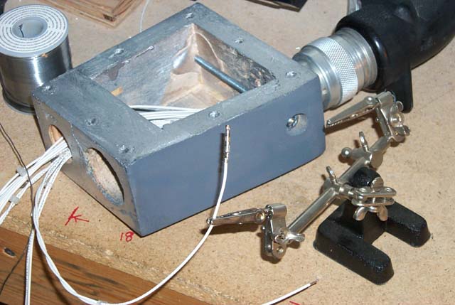
Here's what it looks like after I've finished soldering up and installing the
AMP connector. I've also test-fitted the shaft that will join the SFS box
to the flight stick that is part of the airframe.
The construction of the SFS box is very simple. I used 1/2" plywood
throughout. The SFS box shape is actually what is found in the E model
of the F-15 and I'm using it here because I was only able to obtain
dimensions for the E version. If I ever get the needed info for the C model
SFS box, I'll build a new one.
The box is coated with a thin layer of Bondo that was then finish sanded &
painted. The box cover is attached with 8 machine screws thread into special
threaded inserts that were installed.
Here's what it looks like after I've finished soldering up and installing the
AMP connector. I've also test-fitted the shaft that will join the SFS box
to the flight stick that is part of the airframe.
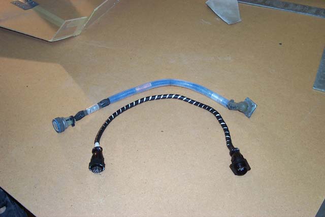
 In addition to building a new SFS box, I had to replace the original SFS cable
that joined the SFS electronics to the flight computer. The image below
shows both cables. The original SFS cable is above and my new cable is under-
neath it.
(The sign in the upper right corner of the image reads:
"Due to current financial constraints, the light at the end of the tunnel
will be turned off until further notice.")
In addition to building a new SFS box, I had to replace the original SFS cable
that joined the SFS electronics to the flight computer. The image below
shows both cables. The original SFS cable is above and my new cable is under-
neath it.
(The sign in the upper right corner of the image reads:
"Due to current financial constraints, the light at the end of the tunnel
will be turned off until further notice.")
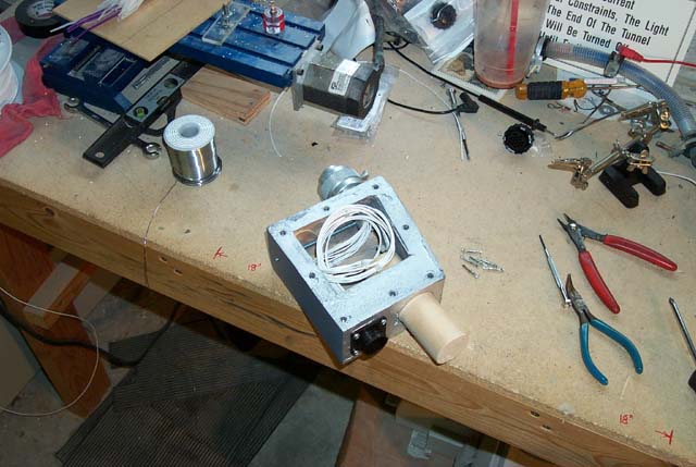
 The next two images show the SFS box fully assembled with the control cable attached.
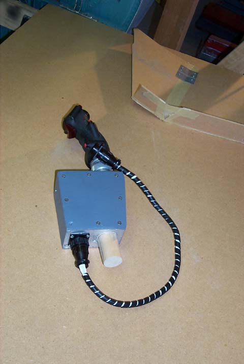
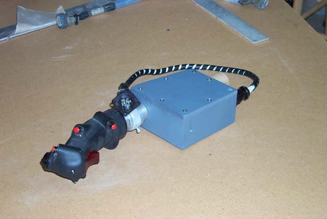 The AP Disconnect & Nosewheel Steering lever is missing from the SFS box.
This was intentional and will be installed soon.
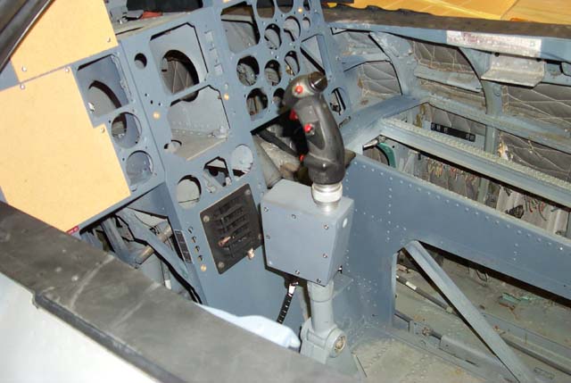
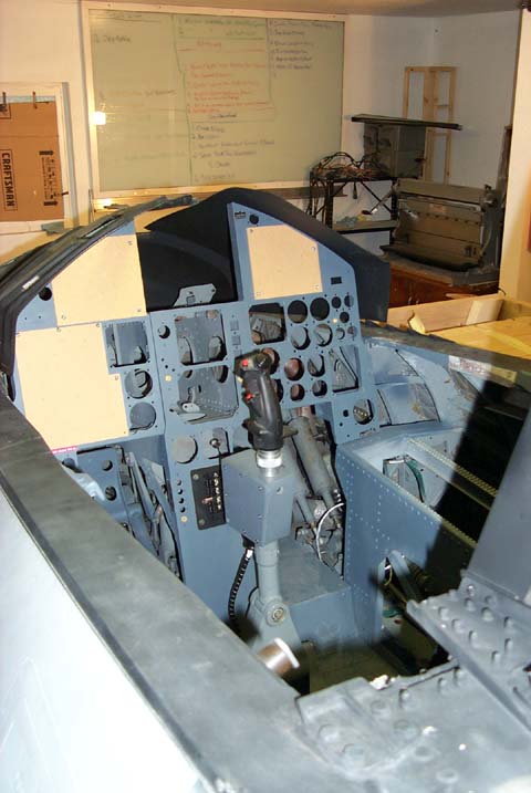
Finally we get to the goal! The next two pictures show the assembly installed
atop the flight stick. The only work left to do here is to install the SFS
cable and bolt in the assembly.
The AP Disconnect & Nosewheel Steering lever is missing from the SFS box.
This was intentional and will be installed soon.
Finally we get to the goal! The next two pictures show the assembly installed
atop the flight stick. The only work left to do here is to install the SFS
cable and bolt in the assembly.