August 10th, 2003
A few weeks ago, I was lucky enough to find the "Big Four" cockpit displays
for the F-15C. This page concerns the VSD or Vertical Situation Display.
The VSD is the radar display for the F-15C Eagle.
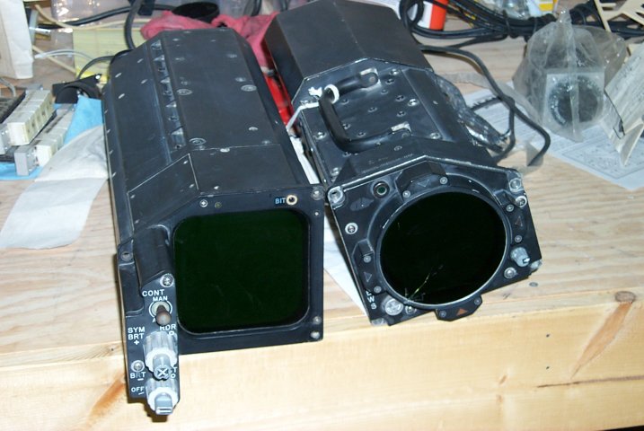 The unit on the left is the VSD display and on the right is the ALR-56
Countermeasures display.
No pictures were taken during the disassembly of the VSD. It wasn't
pretty. I used my wire-cutters a _lot_. I imagine had it been
shown, some poor tech at the Robbins ALC would start sobbing in his
beer. :)
The VSD utilizes a 1:1 aspect ratio CRT. This means that the display
width is equal to its height and the pixels on the screen are square.
This presents a huge problem when rebuilding something like this. The
CRT had taken an incredible shock when the donor jet crashed, resulting
it becoming a nice coversation piece and nothing else.
Square CRTs are obtainable, but they're VERY expensive. So much so
that replacing the original with a like unit was not feasable. The
replacement chosen was a 5" Monochrom VGA display made by Z-Axis.
This type of CRT has a 4:3 aspect ratio, just like your TV set or
computer monitor. The disadvantage to this is that it's not the right
size to fit in the original space that the original CRT occupied. The
width was ok, but the height is too short.
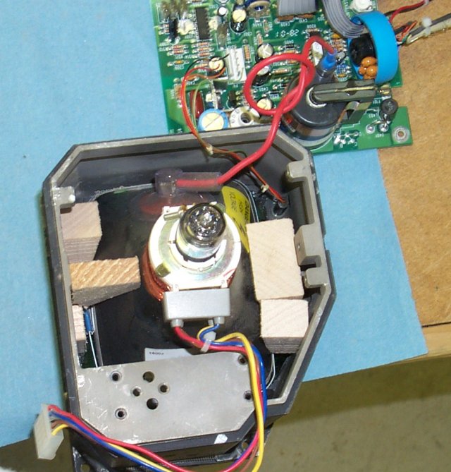
To fit the new CRT into the VSD enclosure head, I had to get a bit
inventive.
The wood blocks support the tube from the back. They've been fixed in
place with a silicone adhesive. The main bottom block is also screwed
into the chassis itself. This works pretty well all things
considered. The face of the VSD is plastic and Rob glued a green
filter made of translucent plastic to it. The CRT is bascially
sandwitched between the wood blocks and this sheet of plastic. It
won't take a hard shock, but it works quite well.
The unit on the left is the VSD display and on the right is the ALR-56
Countermeasures display.
No pictures were taken during the disassembly of the VSD. It wasn't
pretty. I used my wire-cutters a _lot_. I imagine had it been
shown, some poor tech at the Robbins ALC would start sobbing in his
beer. :)
The VSD utilizes a 1:1 aspect ratio CRT. This means that the display
width is equal to its height and the pixels on the screen are square.
This presents a huge problem when rebuilding something like this. The
CRT had taken an incredible shock when the donor jet crashed, resulting
it becoming a nice coversation piece and nothing else.
Square CRTs are obtainable, but they're VERY expensive. So much so
that replacing the original with a like unit was not feasable. The
replacement chosen was a 5" Monochrom VGA display made by Z-Axis.
This type of CRT has a 4:3 aspect ratio, just like your TV set or
computer monitor. The disadvantage to this is that it's not the right
size to fit in the original space that the original CRT occupied. The
width was ok, but the height is too short.
To fit the new CRT into the VSD enclosure head, I had to get a bit
inventive.
The wood blocks support the tube from the back. They've been fixed in
place with a silicone adhesive. The main bottom block is also screwed
into the chassis itself. This works pretty well all things
considered. The face of the VSD is plastic and Rob glued a green
filter made of translucent plastic to it. The CRT is bascially
sandwitched between the wood blocks and this sheet of plastic. It
won't take a hard shock, but it works quite well.
 After allowing time for the silicone adhesive to dry, it was time to
start reassembling the VSD.
After allowing time for the silicone adhesive to dry, it was time to
start reassembling the VSD.
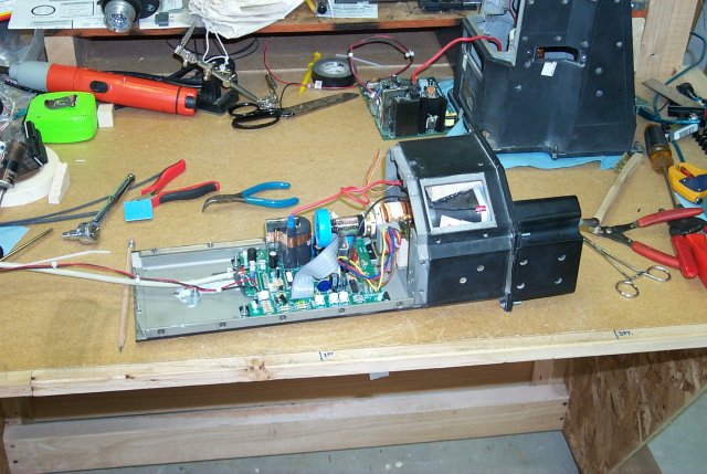 The placement of the display logic board for the CRT had to be done
very carefully since the lead lengths were so short. I glued down four
tie-wrap holders and then attached the logic board by tie-wrap. I
should have used regular stand-offs for this, but I didn't have any
handy. If I ever have to replace the CRT I will correct this error.
The placement of the display logic board for the CRT had to be done
very carefully since the lead lengths were so short. I glued down four
tie-wrap holders and then attached the logic board by tie-wrap. I
should have used regular stand-offs for this, but I didn't have any
handy. If I ever have to replace the CRT I will correct this error.
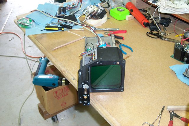 You can see here how the CRT doesn't take up the full space. When the
VSD is re-installed and the VSD camera mount is re-installed, you won't
be able to see the extra space. It only shows up due to the large
amount of light coming in from the front. In the dark simulator
cockpit, this won't be a factor.
You can see here how the CRT doesn't take up the full space. When the
VSD is re-installed and the VSD camera mount is re-installed, you won't
be able to see the extra space. It only shows up due to the large
amount of light coming in from the front. In the dark simulator
cockpit, this won't be a factor.
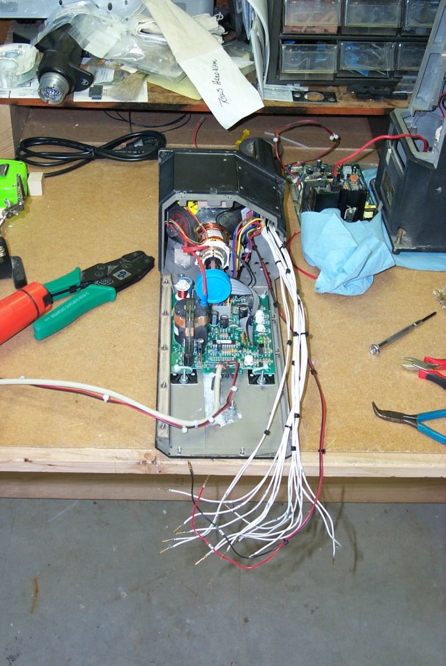 The original contrast, brightness, symbol and radar brightness
controls along with the power and AUTO/MAN switch were stripped,
cleaned and rewired before being re-installed. This wire bundle will
be attached to a 25 pin D connector. The CRT controls will be
connected at a later date and the symbol/radar control will be
controlled via software.
The original contrast, brightness, symbol and radar brightness
controls along with the power and AUTO/MAN switch were stripped,
cleaned and rewired before being re-installed. This wire bundle will
be attached to a 25 pin D connector. The CRT controls will be
connected at a later date and the symbol/radar control will be
controlled via software.
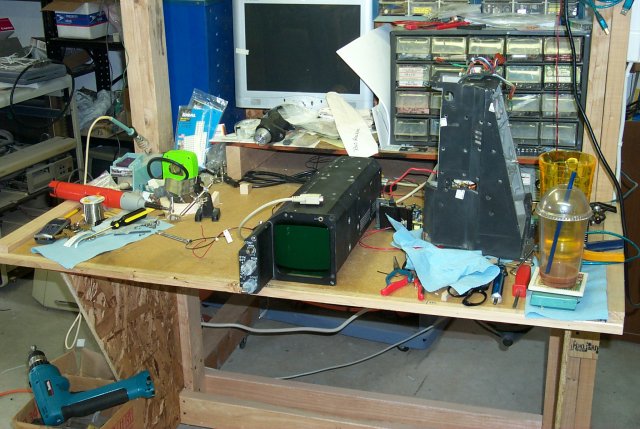 This is the fully reassmbled unit. The VSD chassis itself consists of
the main "head" piece followed by three "shell" elements and the rear
plate.
I had to make sure I hadn't killed the CRT with all the handling it had
been subjected to...
This is the fully reassmbled unit. The VSD chassis itself consists of
the main "head" piece followed by three "shell" elements and the rear
plate.
I had to make sure I hadn't killed the CRT with all the handling it had
been subjected to...
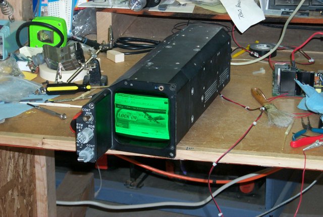 Now of course, I had to use my favorite simulator as the test
screen, right?
The image tearing and shape problems are caused by the contrast being
set WAY too high and the frequency of the display input being off.
Now of course, I had to use my favorite simulator as the test
screen, right?
The image tearing and shape problems are caused by the contrast being
set WAY too high and the frequency of the display input being off.
Back to the Tech Index