I hope you all had a nice holiday!
The fuel panel is now complete with the exception of some clean-up paint work on the PCB and a nick or two on the edge-lit panel.
In order of assembly:
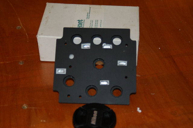
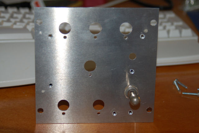
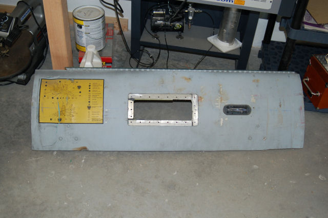
The panel mounting plate. The panel is made from .062" 6061 Aluminum and as previously mentioned, was cut out on my Shop Bot.
You can see video of the panel being cut out here: http://www.youtube.com/watch?v=ccCSD9LjqPI
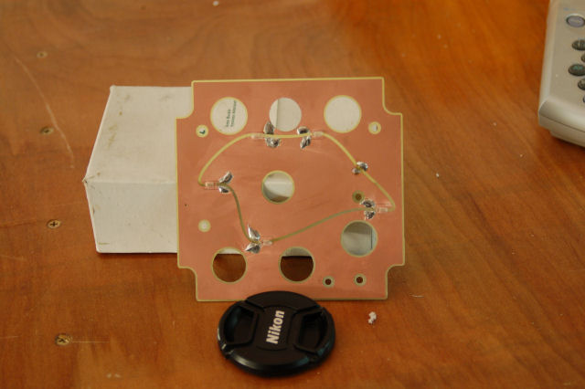
The printed circuit board for the lamps. This is a single-sided copper clad board that is .0313" thick. The copper layer is
somewhere in the neighborhood of .005". The PCB was cut out and routed on the Shop Bot. I used a two-flute .0625" end mill to
cut the board out as well as engrave the circuit path and border areas. The 'bot has fine enough control that I'm able to just
take away the copper layer without going into the epoxy glass board underneath.
The lamps are standard T1 size incandescent bulbs. They run on 5VDC and take about 155mA each. This is very close
to the lamp specified by the MIL-STD for panels, but they're not so damn expensive. :)
The power connector is just a simple 2 pin connector on .100" centers. It's basically the same thing as what is used for
a single-position jumper you'd find on a computer motherboard.
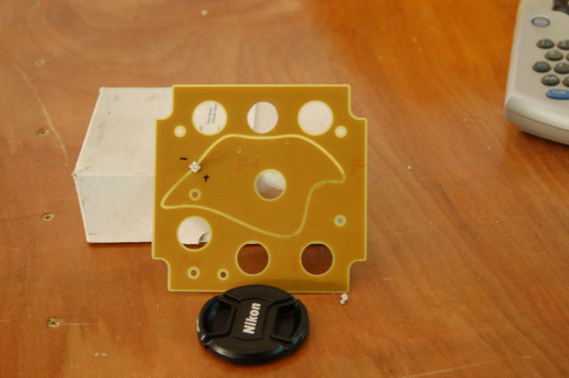
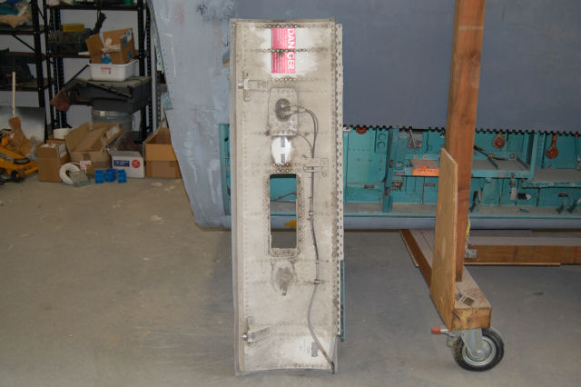
The edge-lit panel. As mentioned earlier, this panel was cut out by laser and all the pocketing in the back was done by 'bot.
Each lamp pocket has a small bit of aluminum foil at the bottom. This serves to prevent any light "hot spots" and it also
helps prevent damage caused by the heat given off by the lamp.
The panel was shot with four coats of FS white, followed by four coats of FS black. I then masked the panel, did all the engraving
for the lettering and re-shot with FS white. After the mask was removed, the panel was shot with four layers of
Testors Dullcote to protect the finish. The result is fantastic to say the least.
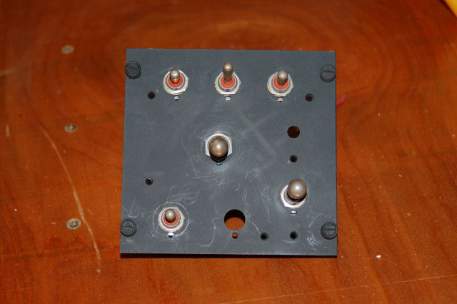
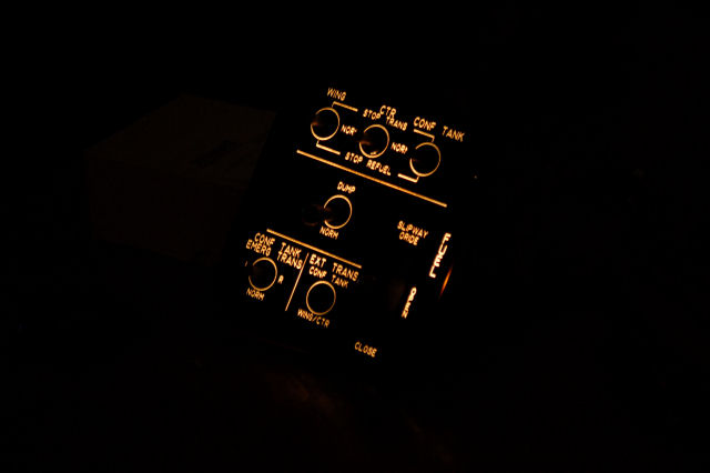
This is the panel assembled and powered up.
The picture was extremely difficult to take so there is a bit of blurring going on. I picked two of the best out of the series
that show the illumination. The light looks brighter in the "lowlight" picture, but that is strictly an artifact from the camera.
The light level coming from the panel never changed between photos.
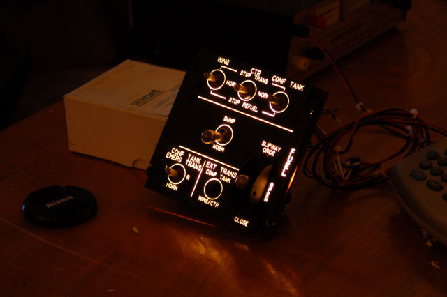
There is a little bit of leakage around the PCB visible - this is due to not having yet painted the PCB. When it's painted,
it won't show light through the edges light it does in the two photos above.
As you can see, there are no "hot" spots, although there are a couple of areas that are just a little bit dimmer than the rest
of the panel. This could be cured by adding another bulb or two. Considering the bulb count and positioning was "best guess",
I think I did pretty well. :) On the other panels I build, I'll err on the side of more bulbs than fewer.
I need to find a single on-off-on toggle switch to complete this panel. I could have sworn I had all the ones I needed for this
panel, but it turns out I'm short by one. Go figure. :)
The next panel up will be the Electronic Warfare panel. This one is really small and simple, with only three switches present.
Pictures of that will follow soon.
Thanks for visiting and have a Happy New Year!
The laser & ShopBot differ just a little bit and it resulted in the holes that the laser cut being just a
little bit off. Fortunately, the error isn't enough to prevent the pocketing on the back to interfere
with the switch mounting hardware.
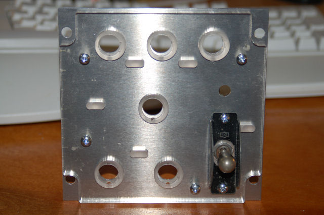
The back plate is made from .062 6061 Aluminum.
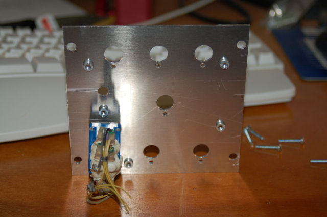 I use a self-clinching nut called a PEM fastener to hold the acrylic edge-lit panel to the backplate.
I'm also using them to hold the switch guard in place. On the original panel, the switch guard is actually
riveted in place on the acrylic panel itself. I didn't want to risk the panel being damaged accidentally,
so didn't go that route.
I use a self-clinching nut called a PEM fastener to hold the acrylic edge-lit panel to the backplate.
I'm also using them to hold the switch guard in place. On the original panel, the switch guard is actually
riveted in place on the acrylic panel itself. I didn't want to risk the panel being damaged accidentally,
so didn't go that route.
As of right now, both the edge-lit panel and the back plate are painted and ready to go. I wanted to give the panel a full 24 hours to dry so I won't be lettering it until tomorrow or the next night. I'll be sure to post pictures of the panel when it's done!
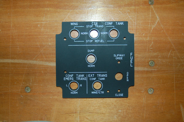
This was produced to test out the processes I had created in order to build the new panels I needed
to have. In my haste to see how it would look, I didn't let the white paint dry completely, but it's a prototype
so I don't feel bad about the minor little defects on the panel.
I'm really looking forward to getting the rest of these completed and installed!
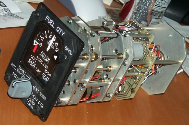
At the end of all this work will be a Type 5 panel. A Type 5 panel is basically an internally illuminated plastic panel that has a printed circuit board installed that holds all the lamp assemblies and the power connector for the lamp. I'll be posting pictures of the entire assembly when I've got it completed.
I'm going back to the shop now, bye! *laughs*
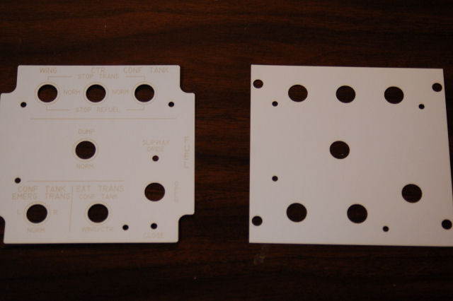
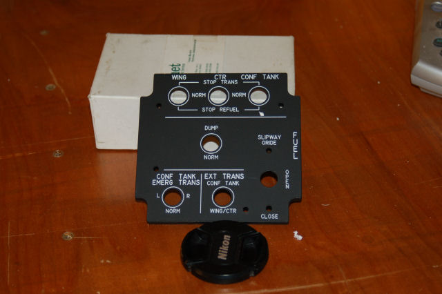
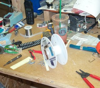
The parts in the picture have been cut out on a laser and are made of heavy card stock. By cutting out the panel
designs in paper first, I can avoid costly errors in plastic and metal.
The image on the right is the edge-lit panel and the part on the right is what the metal mounting plate looks like.
The metal plate is where the all the hardware is mounted, although the Slipway Override switch guard is actually
mounted on the panel itself.
I'm still missing the height of the other panels I need to make, so if the requests I made don't pan out, I'll have
to scale the PDF drawings to the correct width and hope the height comes out right. Since the panels are all designed
according to the Military Specification MS25212 (Control Panel, Console Type, Aircraft Equipment, Basic Dimensions)
there are a set of hard rules I can follow. This will help immensely in "guessing" the right dimensions of the
new panel designs. For instance, the "height" of the panel will always be a multiple of .375. This ensures that
properly located Dzus fasteners will match the hole centers in the mounting rail, which is also .375.
The copy of MS25212 that I have is pretty hard to read, so when I get a chance I'll create a new version in AutoCAD
and post it for you folks to use in your projects if you need it.
There are a couple of changes I need to make to the metal mounting plate to accomodate anti-rotation washers on the
switches, but I hope to be able to start cutting real material for this panel on Saturday.
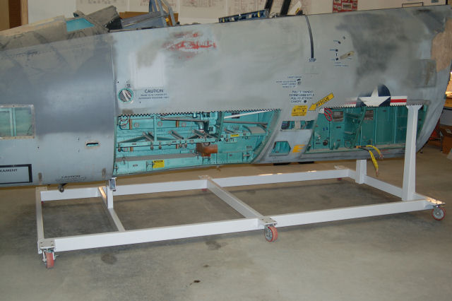
As you can see, the cockpit is supported a lot better now than it ever has been.
The new frame weighs roughly 500lbs and is made of steel box-beam material and industrial strength
wheels.
Click here for more pictures of the new cradle.
My neighbor Mike stopped by with his fork lift and we lifted the cockpit up so we could see what needed to be done to build the new all-steel support frame for it.
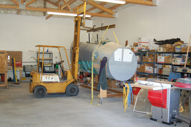
As high as the cockpit was lifted, it seemed very close to the original height it would have been at when sitting on the gear. *wistful sigh*
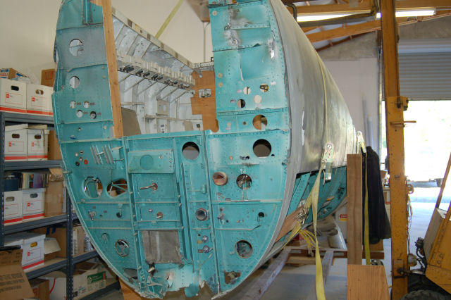
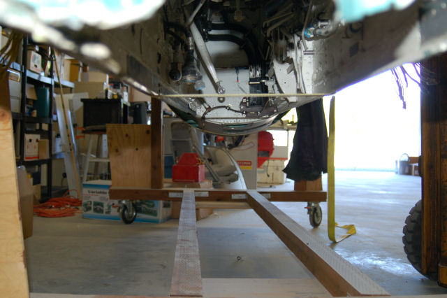
Here's a more detailed shot of the nosegear bay:
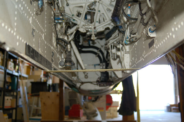
When I first got the cockpit, one of the things I did was attempt to remove the nosegear door that was still attached. Unfortunately, I could never break the sealant that had been used on the hinge line. When we moved the cockpit to the new house, the bottom rested on the transport cradle in such a way that the force broke the sealant loose and the door came free. I haven't been able to remove it until today. Here's a couple of pics:
As soon as the cockpit is set on the new steel frame, work will begin in earnest!
Thanks for continuing to follow the project!
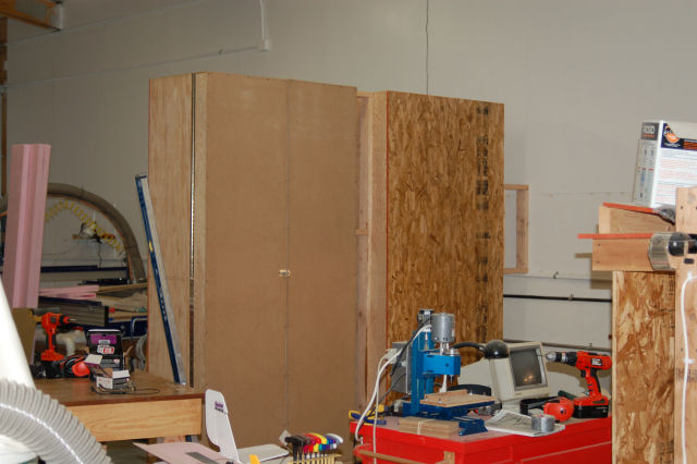
Here's what the new work area looks like right now:
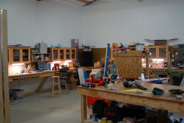
It's a mess right now, but I'm still in the process of getting things organized.
One of the things that I really missed in the old shop was storage space. I may have gone a little overboard in compensating for that prior lack of space. :) I built a pair of cabinets that are 8 feet high, 4 feet wide and 18 inches deep. Joined together they make a 9 foot long dividing wall between the ShopBot and the bench area.
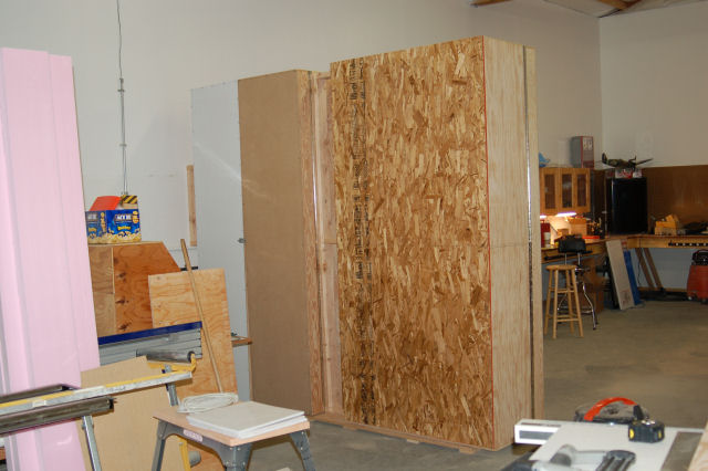
The cabinet doors are 5 inches deep. One side will have shelving
that will hold small tools or parts and the other door has a sheet of
"peg" board that will allow me to hang tools and such on metal hangars
designed for that purpose.
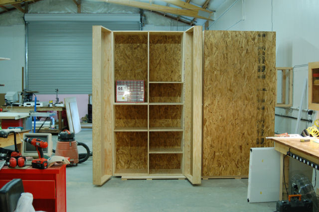
The cabinets have metal track inside that will allow me to put 23x18 shelves in
wherever I need them. This will come in handy if I have to store
something taller than a regular shelving unit could accomodate.
The first 10 "cores" for instrument rebuilding are on the way. I've chosen Beta Innovations AC360 2" gauges to build the new engine instruments, the VVI, backup ASI, AOA indicator and the Cabin Pressure indicator. These gauges are based on air-core motors and are perfect for this kind of work. I still haven't solved the issue with the odometer displays on the RPM, TIT and Fuel Flow indicators, but I'm sure I'll come up with something soon. If I can't find suitable 7 segment or matrix displays, I'll try salvaging some other instruments I have for their mechanical movements.
Massive Update Page #1
Massive Update Page #2
Massive Update Page #3
Massive Update Page #4
Update is complete, thanks for reading!
Last month a heard from a nice gent named Steve about my F-15C. Seems that he had an interesting bit of history for me that no one else had told me about.
It turns out that my jet has a name, and boy did it ever earn it. Here's his story:
I flew RF-4C's at Zweibrucken during that time, but a friend of mine had
just transferred to F-15s and told me the pre-accident story. Later on,
USAFE safety and McDonnell Douglas came around and briefed the accident
with a different video and stories.
First I'll tell you the story of how it was that aircraft 007 was chosen
to perform at the airshow at Soesterberg (pronounced Soo-sterberg) AB
in the Netherlands. Your aircraft was almost brand new to Bitburg AB.
It had arrived from the McDonnell-Douglas factory in St. Louis and had
minimal hours on the airframe (about 10) when one of the pilots took it
on a cross-country mission to Scandinavia.
(I'm not sure of your background, so I'll take a minute to explain
cross-country: A cross-country is where they give you an aircraft for
the weekend and allow you to fly it wherever you want in order to get
training and flying hours for the wing. Generally you are committed to
six sorties - two each Friday and Monday and normally two on Saturday or
Sunday, giving you one day off in a country. In Europe, cross-country's
were critical to maintaining wing flying hours because of the typical
lousy weather over there.)
Anyway, it was summer and the squadron was going to have a big party, so
on Sunday the pilot bought a whole bunch of Norwegian shrimp, which was
packed in its own frozen brine and ice. He stored the boxes of shrimp
in the large area behind the ejection seat Sunday evening. Well, given
the temperatures and the two additional sorties he flew on Monday, there
was naturally some melting and leaking from the boxes behind the seat.
When he landed at Bitburg the pilot spot cleaned the area behind the
seat, but unbeknownst to him the now-liquid brine had made it's way into
lots of areas of the aircraft. Also, little did anyone know the
corrosive effect brine had on aircraft aluminum. After about a week of
flying a crew chief noted lots of rust behind the pilot seat(*). A
closer inspection revealed sheet metal damage, and some corrosion on
wiring and tubing. It was determined that the damage was so extensive
that the regular Wing Level sheet-metal repair shop and maintenance
could not handle the job, so the aircraft had to be sent to F-15 PDM
(Programmed Depot Maintenance).
(*) When the initial rust was discovered and the story of how this
happened came out, and even though the maintenance folks didn't find it
amusing, pilots being who they are could not help but see the humor in
the story and so the aircraft was given a name: "Shrimp Boat". Just so
you know, very few AF aircraft are/were named anymore...so it had to be
something special to actually have an aircraft name all the pilots would
recognize. Most times when you called maintenance after a flight you
just called in the tail number....but 007 was now Shrimp Boat.
As an aside (maybe this is why I remember Shrimp Boat) my squadron had
an aircraft (364) that departed the runway on landing and from then on
was known forever as "Mud Slide". It was the only "named" aircraft in
our squadron. About a year later the aircraft departed the runway again
and the Chief of Maintenance claimed it wasn't a maintenance problem,
but rather pilot sub-conscious because everybody called the aircraft Mud
Slide.
Anyway, after about a month, the refurbished and newly repainted
aircraft returned to Bitburg. The Soesterberg Air Show was coming up.
(Note: Even though Soesterberg was also an F-15 base, the USAFE F-15
Demo pilot was stationed at Bitburg, so that's why a Bitburg F-15 was
performing at Soesterberg). When they choose an aircraft for an
airshow, they try to find the nicest looking aircraft, because in
addition to flying, it is also used as a static display. Well, aircraft
007, aka Shrimp Boat, having just returned from Depot, had a brand new
paint job and it was determined that the Bitburg F-15 Demo Pilot would
fly Shrimp Boat at the Soesterberg Air Show.
THAT, is how your cockpit got to the Soesterberg Air Show....
Note, I agree that the aircraft had 9.5 hours on it when it was accepted
at Bitburg, but not at the time of the crash: this aircraft had flown
from the factory ~ 10 hours, a cross-country ~ 8 hours, a week of
flying, and to/from PDM ~18 hours, and about a week before the airshow,
so it had less than 50 hours total on it when it went to its final
flight at Soesterberg.
Much shorter: The Accident: The following stuff came from the
debriefings after the accident.
There is another, better amateur video out there. Whether or not the AF
confiscated it or not or whether you might find a copy on the internet
is a good question. But the other video shows the entire turn to final,
the crash and slide, the (slightly) humorous post-crash incident, and
the aftermath.
The F-15 has computers to assist the pilot. As he makes the final turn
the folks from safety pointed out the aircraft computers realized there
was a problem and you can watch the stabilator and rudders fighting the
pilot all the way to the ground. As noted in the accident report, after
he slid 1500 feet on the ground the pilot ground egressed safely...but
what you can see quite plainly on the video is that after he runs about
100 yards away from the aircraft, he turns back, looks at the wreck,
removes his helmet and throws it to the ground with his right hand (it's
a lot funnier to watch than to read).
Finally, the folks from McDonnell-Douglas and Pratt & Whitney were quite
proud of the F-15s performance during and post accident. In addition to
the video showing the computers trying to recover from the pilot's
maneuvers, the video showed something else. Look closely at Mr.
Steehouwer's pictures and you'll see what I mean: After the aircraft
slid 1500 feet across the infield you'll notice all the smoke and dust
blowing in the air. That is because after the crash, going across
grass, dirt and rocks and sucking in all of those, the right engine is
still running. The engine continued to run well after the pilot had
egressed and it ran until the fire department was able to get enough
water into it to shut it down.
Pretty damn cool eh? Shrimp Boat. Makes me think of an F-15 with a pair of net cranes instead of wings. :)
Interestingly enough, shortly after Steve sent me that cool story, I got an email from Mario, the webmaster of the Slobberin' Wolfhounds Squadron website. It turns out that he's got a couple of photographs that were taken by an RNLAF Fire Brigade member by the name of Ruud Vrakking. Mario was kind enough to give me permission to use these:
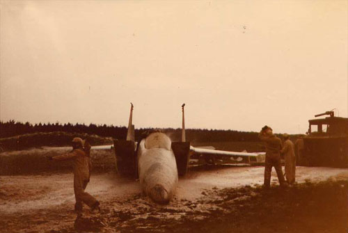
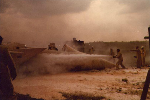
You'll notice that the fireman in the lower picture is drowning the right engine just as Steve mentioned in his story. That is pretty damn cool.
I'd really like to get my hands on that video footage that Steve mentions above. If you know where it's hiding, PLEASE let me know!
We've recently moved and I'm waiting for the shop at the new house to be built before I can resume work on the F-15. The wait is going to drive me out of my mind. At the rate things are progressing, I won't have a shop until June or later. :(
The good news is that the new shop is a lot bigger than the old one. I'll be going from a 42x24 building to a 60x36 with a 14' high cieling. This means that I'll be able to use the canopy I'm going to get soon.
Until next time!
The @f15sim.com email is fixed. I'd accidentally trashed the mx record. *d'oh*
You'll also note a big rework of the Project News page. I hadn't realized how large the page was so I decided to cut it down a bit and move prior year updates to their own page. You can find them here or follow the link at the bottom of this page.
 ...is the third 1,000 foot spool of wire I've used so far. That's right folks,
the F-15C simulator project has officially consumed 3,000 feet of signal wire. :)
...is the third 1,000 foot spool of wire I've used so far. That's right folks,
the F-15C simulator project has officially consumed 3,000 feet of signal wire. :)