

So the printed circuit boards mentioned in the previous entry have been put to work!
The gauge shown here is the core that I’ll build the six 2″ engine gauges out of.
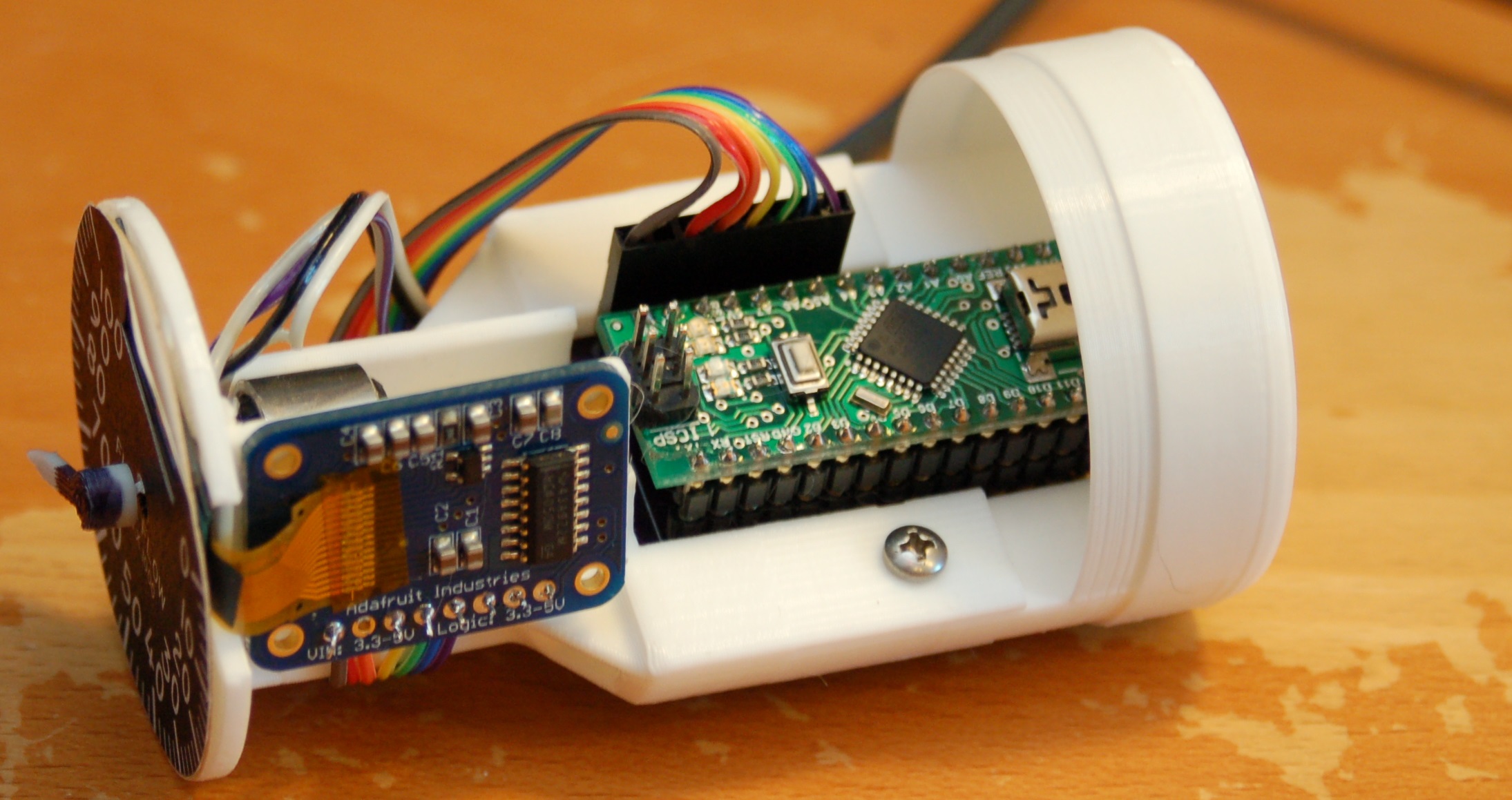
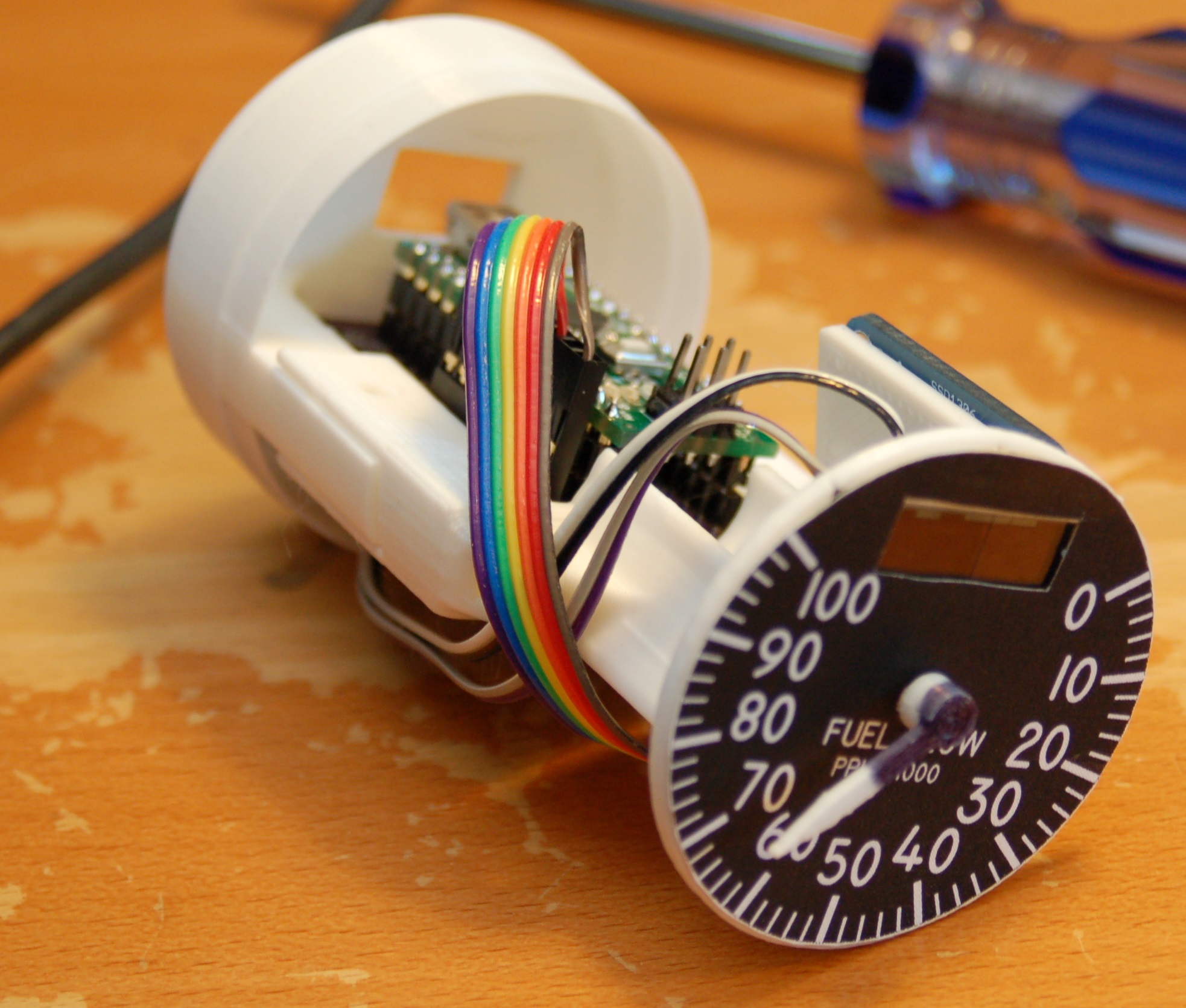
Here’s what the gauge looks like on the inside. All the plastic components (the white bits) are 3D printed on my SeeMeCNC Rostock MAX v1, Orange Menace.
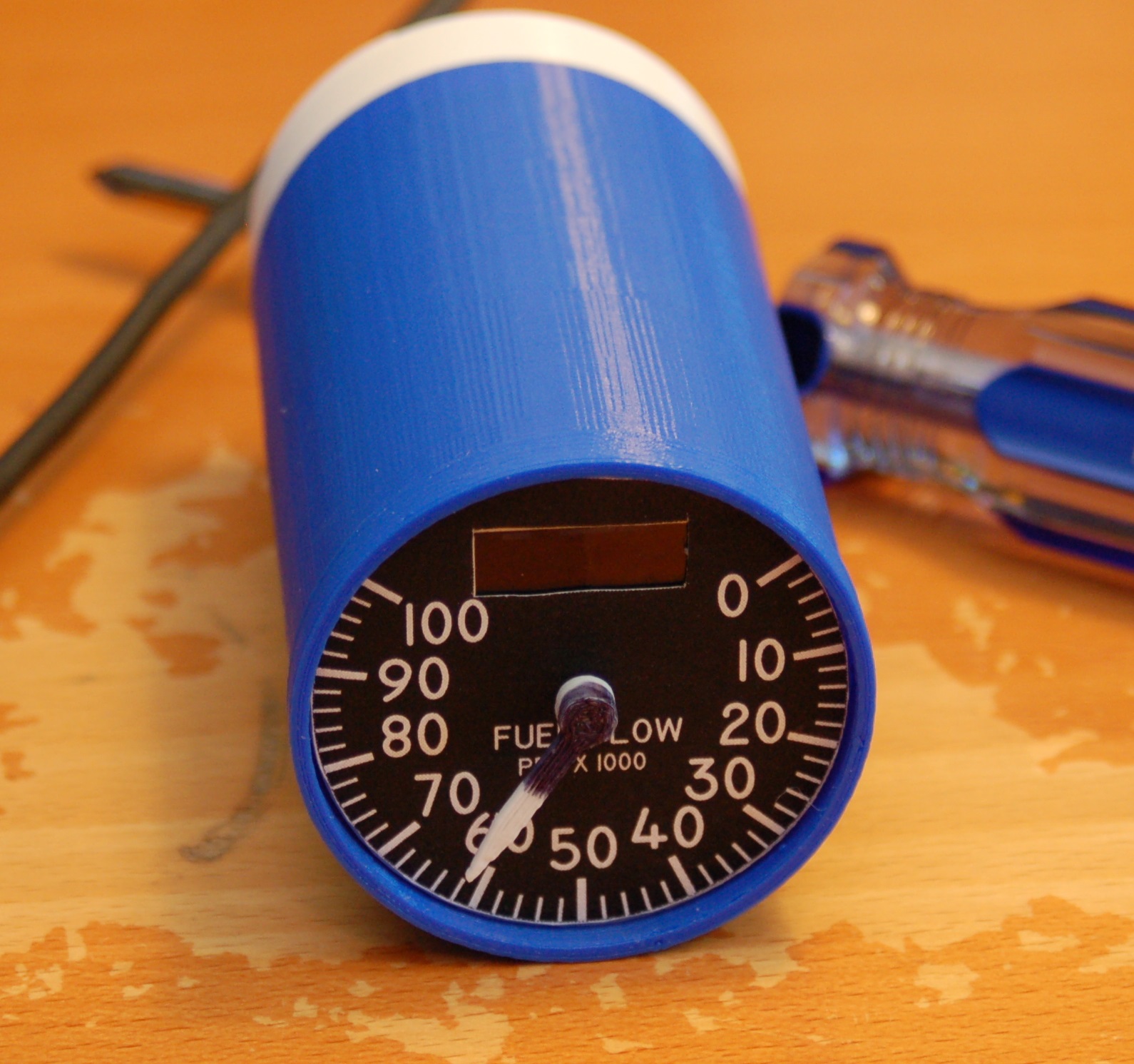
Here’s how it looks with the “test” case on it:
Finally, here’s a short video of the gauge in operation:
Once I have the time, a properly sized case will be printed (the blue one is too short) and I’ll get a good laser engraved face on the gauge.
It’s coming along! 🙂
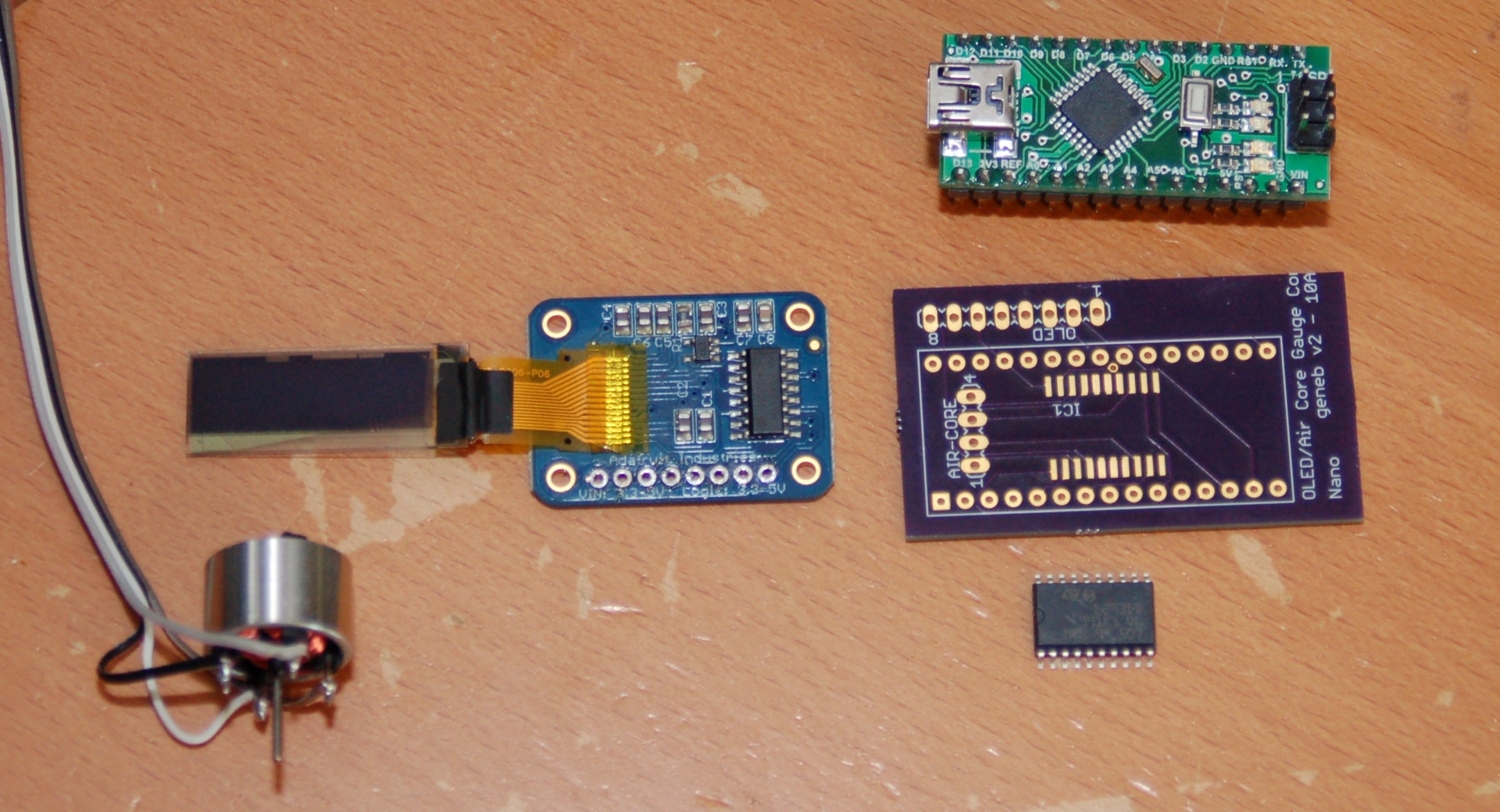
[Here are the gauge electronic components, sans header connectors]
Comments


Powered by WordPress | Copyright © 2026 F-15C Flight Simulator Project. | All Rights Reserved. | Design by Shea Media
steve on 10.05.2015
Keep up the great work! Just wanted to let you know you have fans out here paying attention. Great stuff.
William Owen on 11.19.2015
Gene,
I have watching your progress for several years and am always impressed. You and I share the same ideas about sims. I am a simpits list subscriber but have little to contribute. I was looking at f15sim.com and wondered where you got your aircore motors. As a follower of Mike’s Flight deck, I just cannot see myself fiddling with building from scratch.
Thanks, William
admin on 02.19.2016
I envy you your metalworking skills. I ran across your Tri Pacer cockpit project some months ago. EXCELLENT work! The air core motors were purchased as part of a group buy some 10 years ago. You can buy them from Simco here: http://www.simcoaftermarket.com/specialty-oem/micro-air-core/ for around $22 each in single quantities.
admin on 02.19.2016
Thanks!