Why yes, you CAN buy a missile launch rail…
Not exactly F-15 specific (F/A-18 actually…), but I figured the folks that follow my shenannigans would get a kick out of this. A year(ish) ago, I found a LAU-117/A launch rail for sale on Facebook, and before common sense could override the PayPal transaction, I’d bought the stupid thing.
Enjoy the video!
New scan of the mishap report!
Check out the Library tab above – I’ve scanned the complete mishap report as I received it from the USAF in 2004.
APG-70(V) Radar panel rebuild is complete!
This took a completely unacceptable time to finish. 🙁 I tore down the original panel probably close to three years ago. Life and other projects conspired to push work on the F-15C to the background. Yesterday (9/19/20) I got out of bed with my task for the day to get this panel knocked out. I didn’t get it done in a single day, but damn near. 🙂
I disassembled the APG-70(V) radar panel and stripped down all the switches of the original wiring and carefully de-pinned the Cannon connector. I worked out the connection positions on the switches and got new leads attached. When I originally started this rebuild, I got as far as a single switch and then SQUIRREL!…
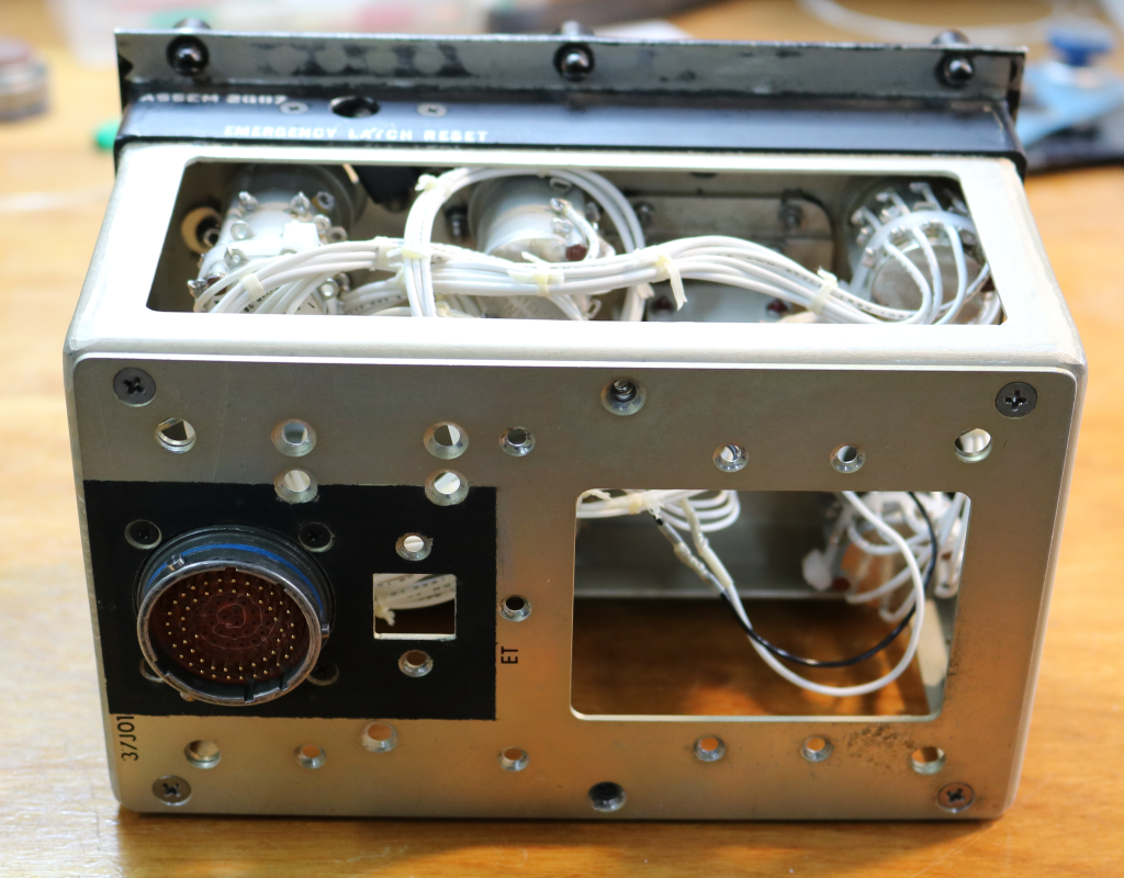
Here’s what the panel components look like prior to final assembly:
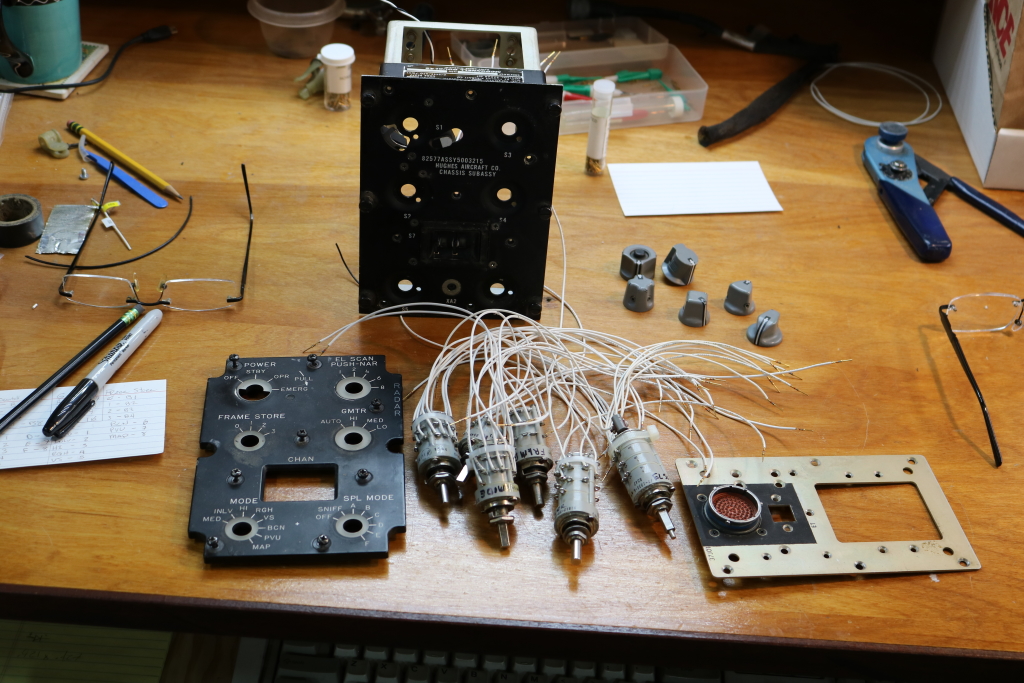
And after installing & pinning the interface connector:
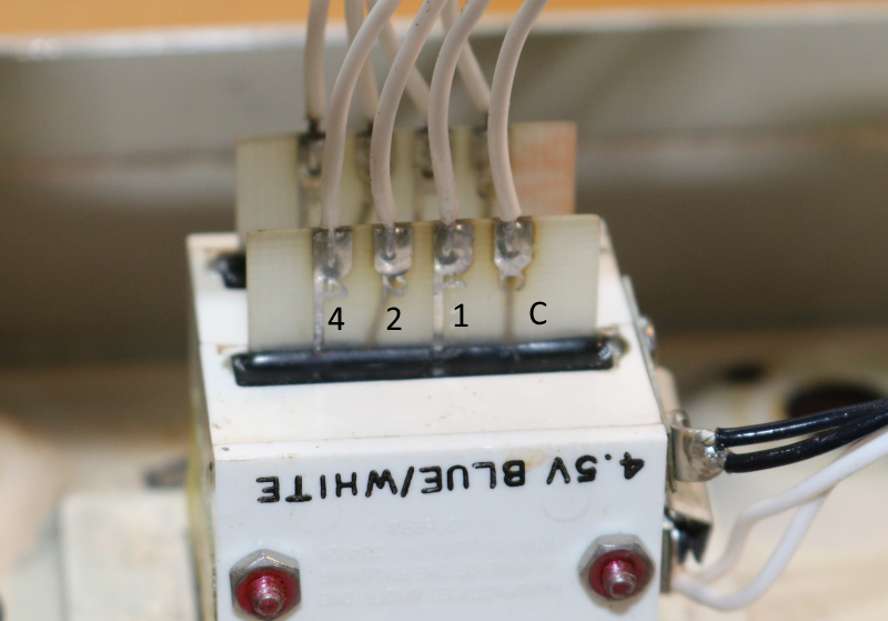
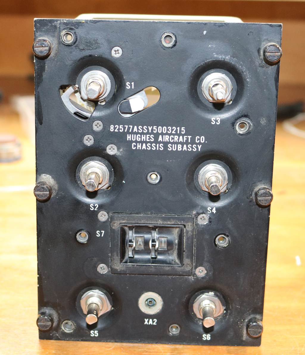
The channel selector is kind of a neat switch. It consists of two 8 position rotary switches. The first is labeled “A” through “H” and the second is “1” through “8”. The switches are BCD – Binary Coded Decimal. There’s a common wire on each and then three terminas, “1”, “2”, and “4”. Those three wires in combination can represent 8 different switch positions.
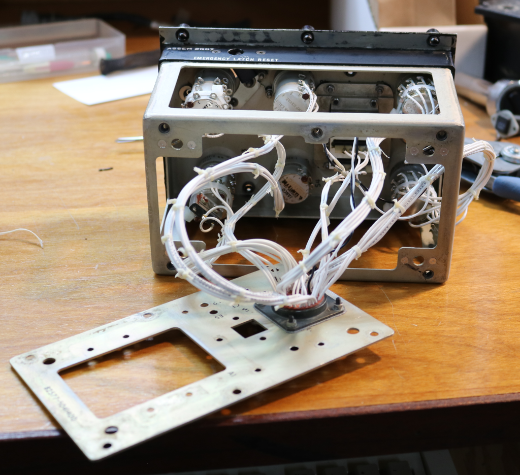
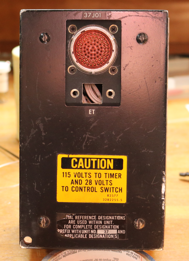
Now the back plate gets mounted. In rewiring the panel, it uses 52 pins on the original Cannon connector:
Now it’s ready for the edge-lit panel and knobs to be installed. Maintainers may spot a problem in this view. 🙂
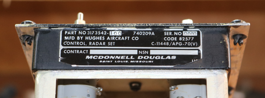
This particular APG-70(V) radar happens to be serial number 0009…
With the knobs back on…
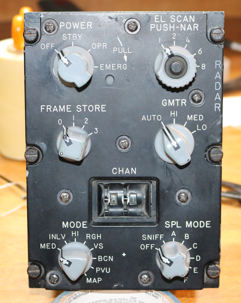
Finally, here it is with the rear shell cover back on:
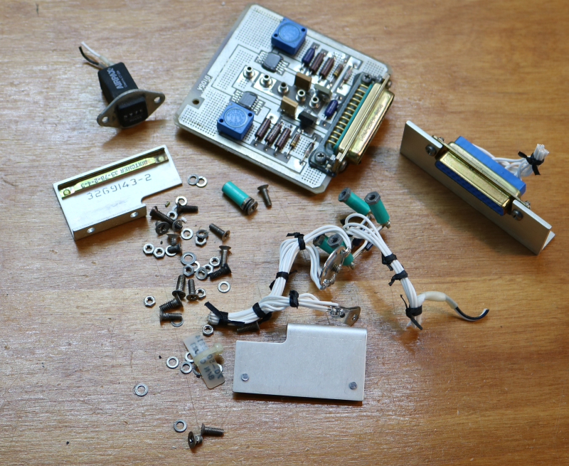
Here’s a pile of the extra bits that I didn’t need…
The next thing I need to do is craft the wiring harness that connects the APG-70(V) panel to the main bulkhead Cannon plug. I’m going to look into either building or buying some kind of automated wire measuring/cutting tool. There’s 52 wires for this panel – it makes for a very tedious work session when most of your time is consumed by measuring and cutting wire…
BTW, if anyone knows how to force WordPress to stop imposing 1:1 aspect ratios on images, please let me know in the comments.
Something new!
If you look above this post, you’ll see a new tab – “Library”. This is where I’m starting to put scans of “official” documentation and literature that I’ve got on the F-15. The first two volumes of Eagle Talk are up already. I’ve got vols III and IV to scan, and those will go up as soon as I can get them scanned. It may be a slow process as running the book scanner enrages my carpal tunnel something fierce. 🙁
[Update 03May19]
Volumes III and IV are scanned and available for download. If you have later volumes, please contact me! I’d love to add them to the collection.
Upcoming live stream!
I’ve been looking into doing live streaming of the panel rebuild work on the F-15. Basically this would be a live stream of me working out the panel wiring, wiring up the connectors and adding the harnesses to the main side console harness.
I’d be narrating what I’m doing as well as answering questions from folks over chat – I’ll be using Twitch to handle the stream.
I’ll likely start doing this on Saturdays at noon(ish) and the stream will run until I get tired of working on the “panel of the day”. 😉
When I firm up a schedule, I’ll post information here as well as in the “usual” places, such as SimHQ, the simpits-tech mailing list and likely Facebook.
See you then!
CAS panel rebuild & wiring harness is complete.
Last Saturday I took some time do de-pin the cannon plug in preparation for rebuilding the CAS panel. This weekend I finally got around to getting that panel rebuilt and wired into the left side console harness.
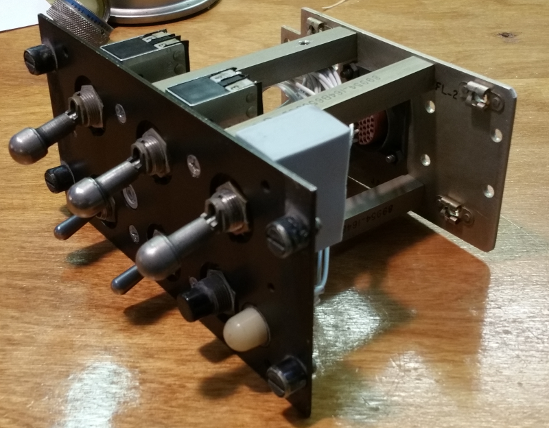
Here’s a few pics of the rebuilt panel assembly:
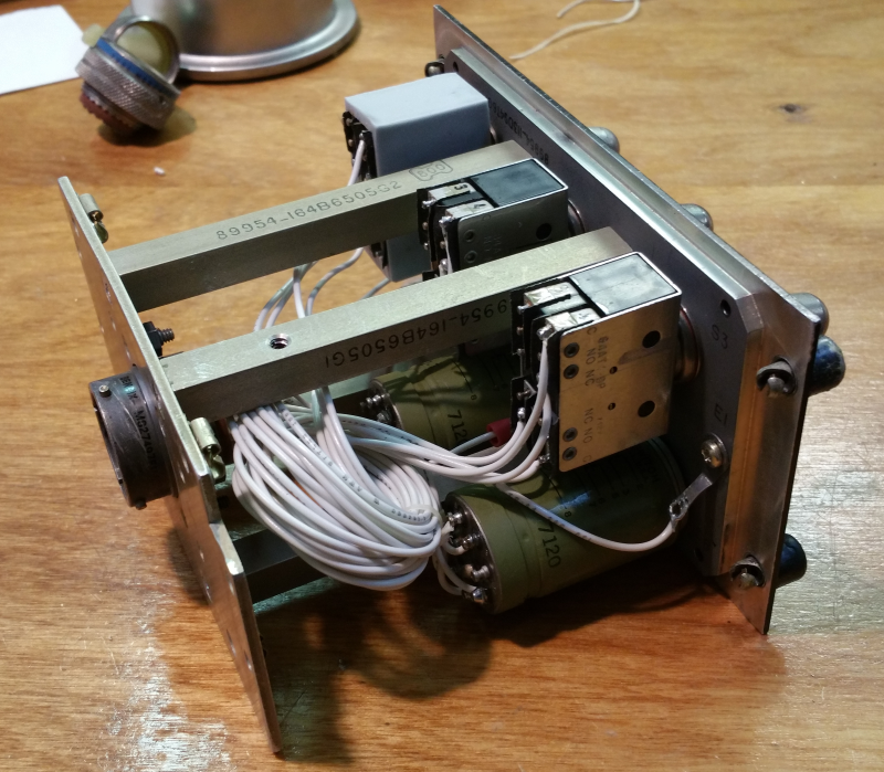
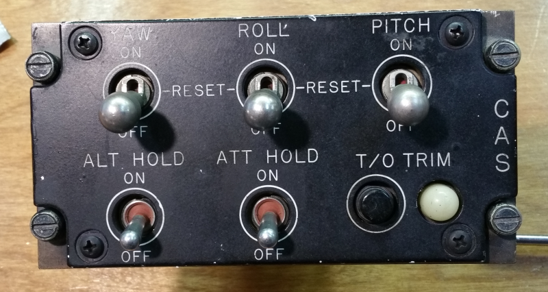
The CAS panel is interesting in that it’s got a pair of magnetically held toggle switches. It’s essentially a relay that’s designed with a very heavy spring to keep it open unless the coil is holding it closed. Here’s what one looks like:
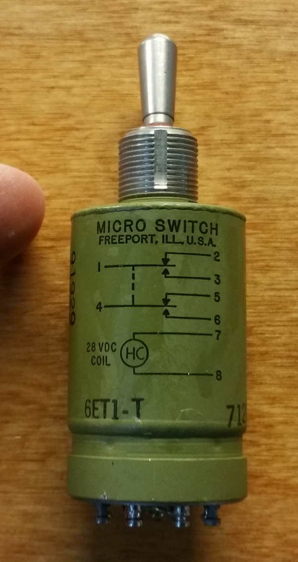 Fingertip for scale. 🙂
At some point I’ll post the little video I did that shows how the switch operates.
It turns out that I may have a pretty special CAS panel. I noticed the manufacture date & serial number on the back of the edge-lit panel:
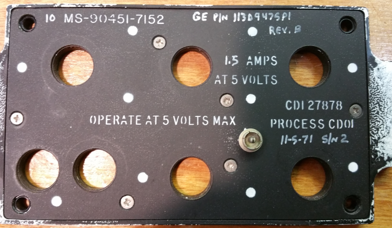
The date is November 5th, 1971 with a serial # of 2. This makes me think that the panel may be from one of the original test articles that MD built, but I’m not sure. I’ll update this post if I find out more information.
New gauge design!
I spent quite a while working on getting the air core motors to work properly. The biggest issue was the sound they made due to the PWM signal resonating in the instrument shell. I did get the sound to go away, but at the required frequency the motor would no longer move properly. This lead me to look into other methods I could use that would still fit into a 2″ MS33639 instrument shell.
Many years ago I briefly looked into the micro stepper motors made by Switec. They were fairly new on the scene and were nice, but expensive motors. Fast forward about 12 years and I find that you can obtain these motors for as little as $2.50 each! (lot of 25 on eBay) My search for more information on the motor led me to an Arduino project where the goal was to use these steppers in various projects. The cool thing is that due to the low power consumption of the coils, they could be directly driven from an Arduino without the need for an h-bridge chip! (20mA per coil) The blog entry that I found is here: http://guy.carpenter.id.au/gaugette/2012/01/05/what-is-gaugette/ – I’d recommend you read the rest of his blog – there’s a ton of great information on using Switec motors, including with a Raspberry Pi.
I did a bit more research and found a demonstrator project on Tindie that used a Switec motor – https://www.tindie.com/products/TheRengineer/analog-gauge-stepper-breakout-board. The board allowed for easy connection to an Arduino and included clamping diodes to prevent back-EMF from doing damage to the Arduino. Since the board was way too large for my needs, I re-designed it to use surface mount diodes (LL4148) and reduced the size of the board to match the diameter of a Switec motor.
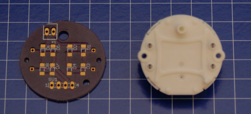
The 4 pin connector along the bottom is for the two coils in the motor and the 2 pin connector at the top is for the 5v reference voltage for the diodes.
I revised my gauge code to use the Switec X25 library and it works great! The motor I’m using is the X27.168 and has an internal stop. The 2″ gauges in the F-15 don’t require more than 300 degrees of rotation at the most, so this is a perfect choice – it allows me to rotate backwards to hit the stop and then start from a known point. The idea being to use the stop in lieu of a “home” position detector.
Unfortunately, changing to the Switec motor required that I completely re-design the “middle” section of the gauge.
Here’s the result of that redesign:
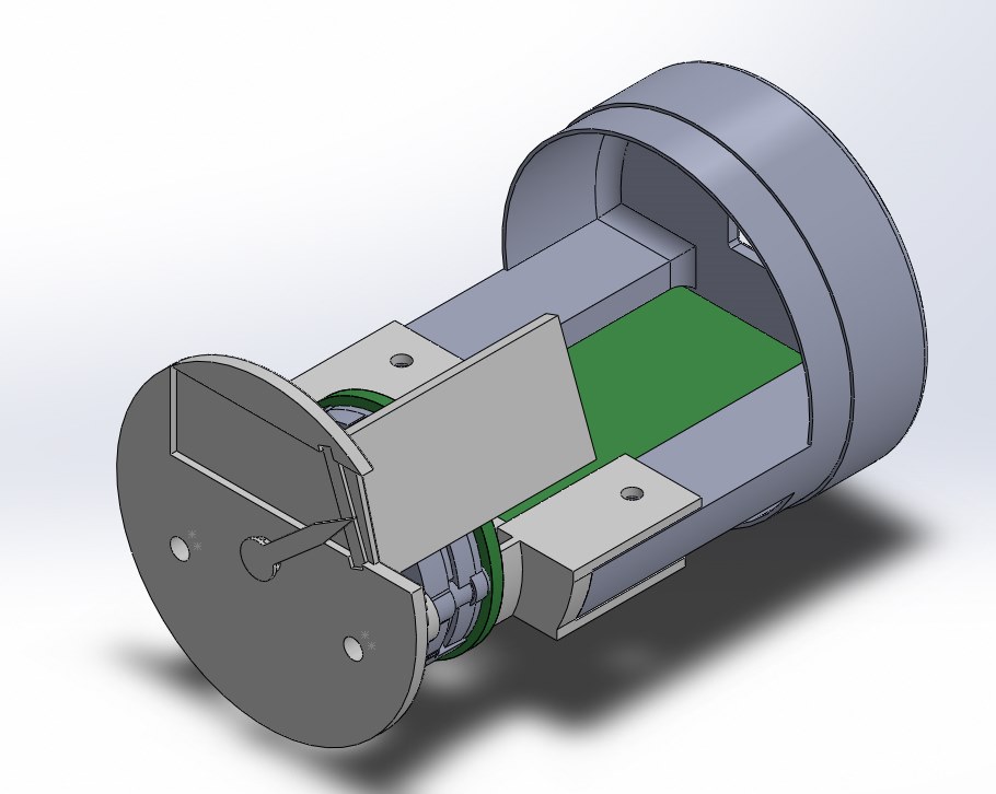
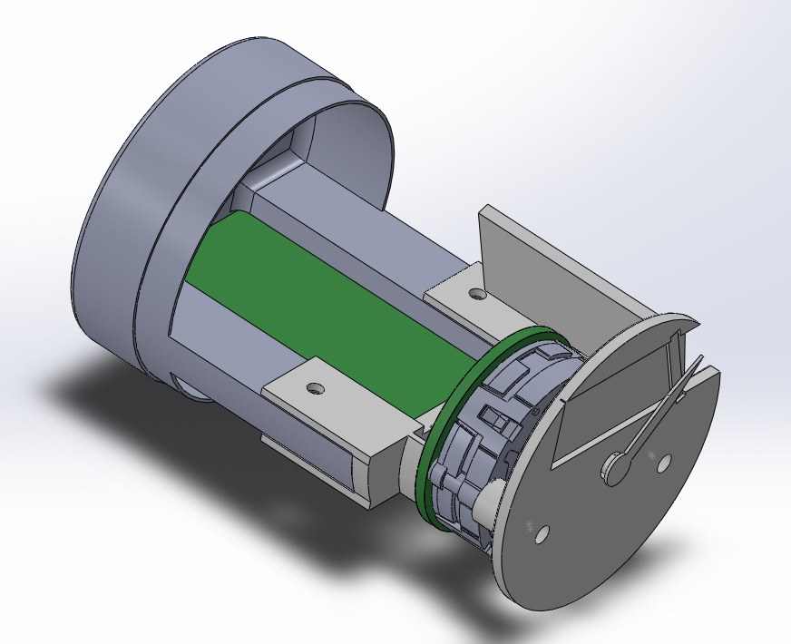
The resulting assembly is going to be roughly 3/4″ shorter than the original, air-core based design. I’m currently printing the new components as I write this. The photo below is the new center mating clip.
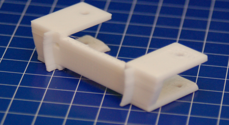
This part attaches to the back half of the instrument using two screws. It is connected to the motor and instrument face using a pair of 0-80 screws that pass through the stepper motor and end up in heat-set inserts installed in the standoffs on the instrument face.
I also got the chance to get the finishing touches done on the gauge face graphics. I had them printed up on 120lb card stock at Staples:
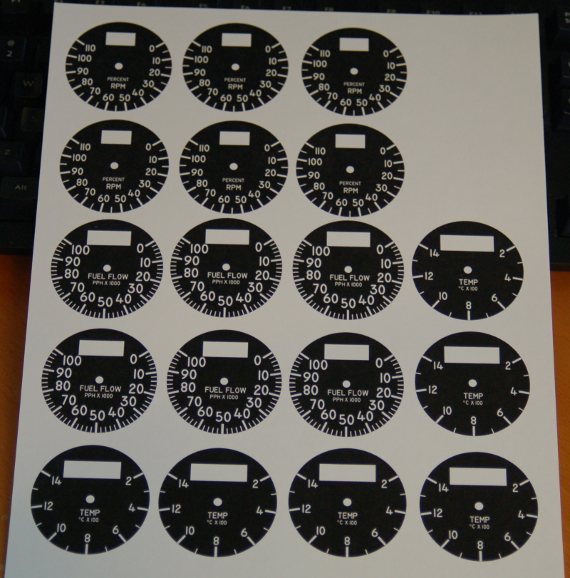 The plan is to cut them out on the laser and then glue them to the gauge faces after assembly. I had enough made to ensure that I’ll have spares when I inevitably screw one up. 🙂 I really like how they turned out!
Thanks for reading!
Update on the 2″ gauge.
I finally had the time to come back to the gauge and get the firmware finished!
I had somehow managed to do damage to the Arduino Nano such that you couldn’t upload firmware to it using the “normal” method in the Arduino IDE. Turns out I’d blow the rxdata line going into the ATMega 328 MCU on the board. 🙁 The good news is that I’ve got it replaced and the firmware is done. Next step is to make some high quality faces, new needles and new instrument shells.
Here’s an interesting bit of trivia for you – the F-15C can consume up to 150,000lbs of fuel per hour at low altitude and in full afterburner. That’s right around 22,000 gallons of fuel per hour! Those F100-PW-220 engines are hungry! 🙂
2in. Gauge design is complete and tested.
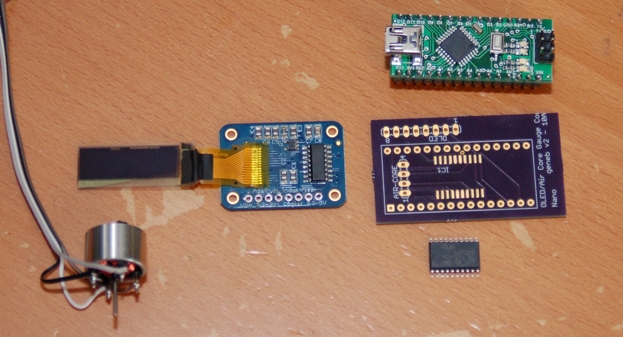
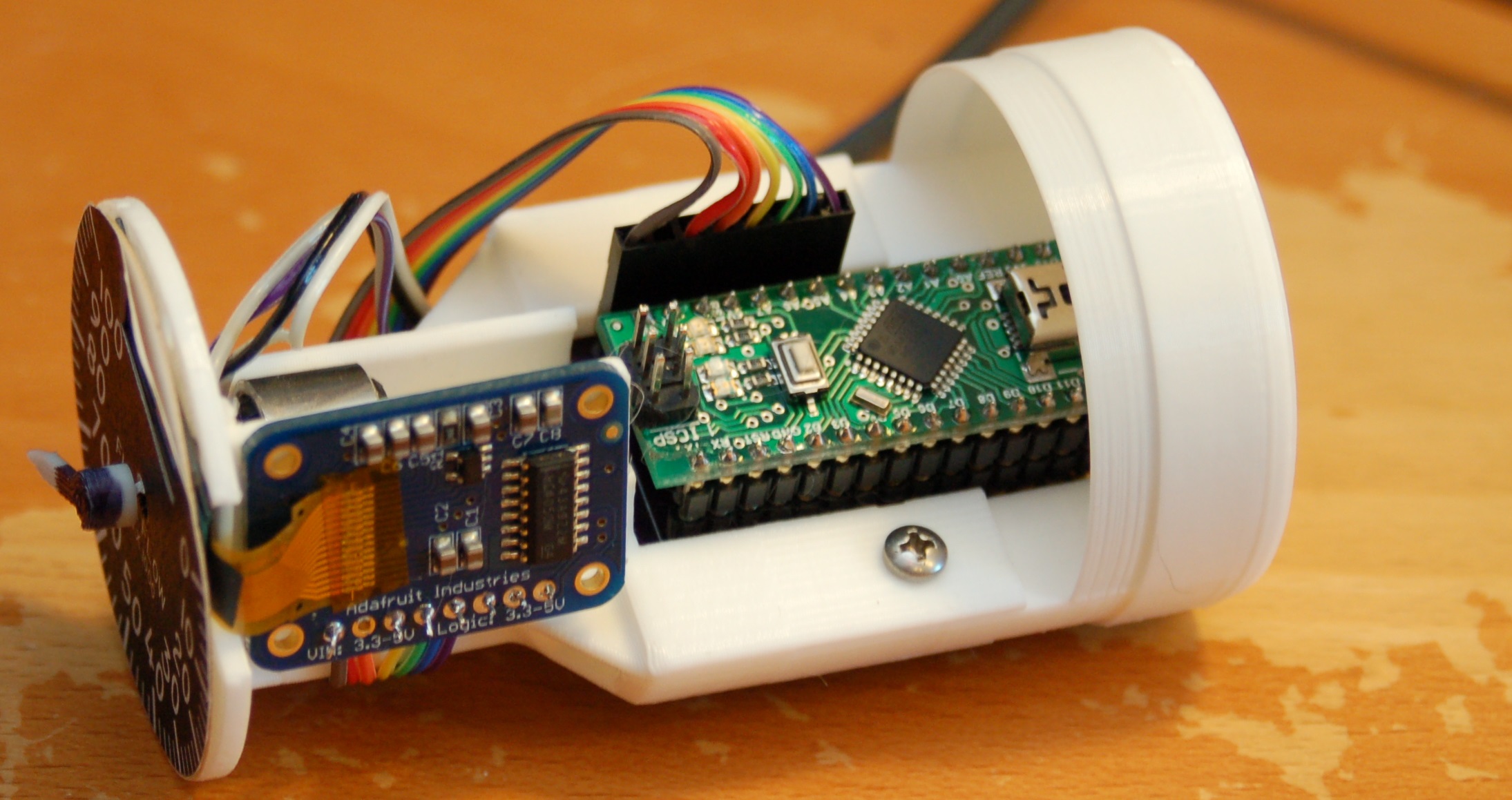
So the printed circuit boards mentioned in the previous entry have been put to work!
The gauge shown here is the core that I’ll build the six 2″ engine gauges out of.
Here’s what the gauge looks like on the inside. All the plastic components (the white bits) are 3D printed on my SeeMeCNC Rostock MAX v1, Orange Menace.
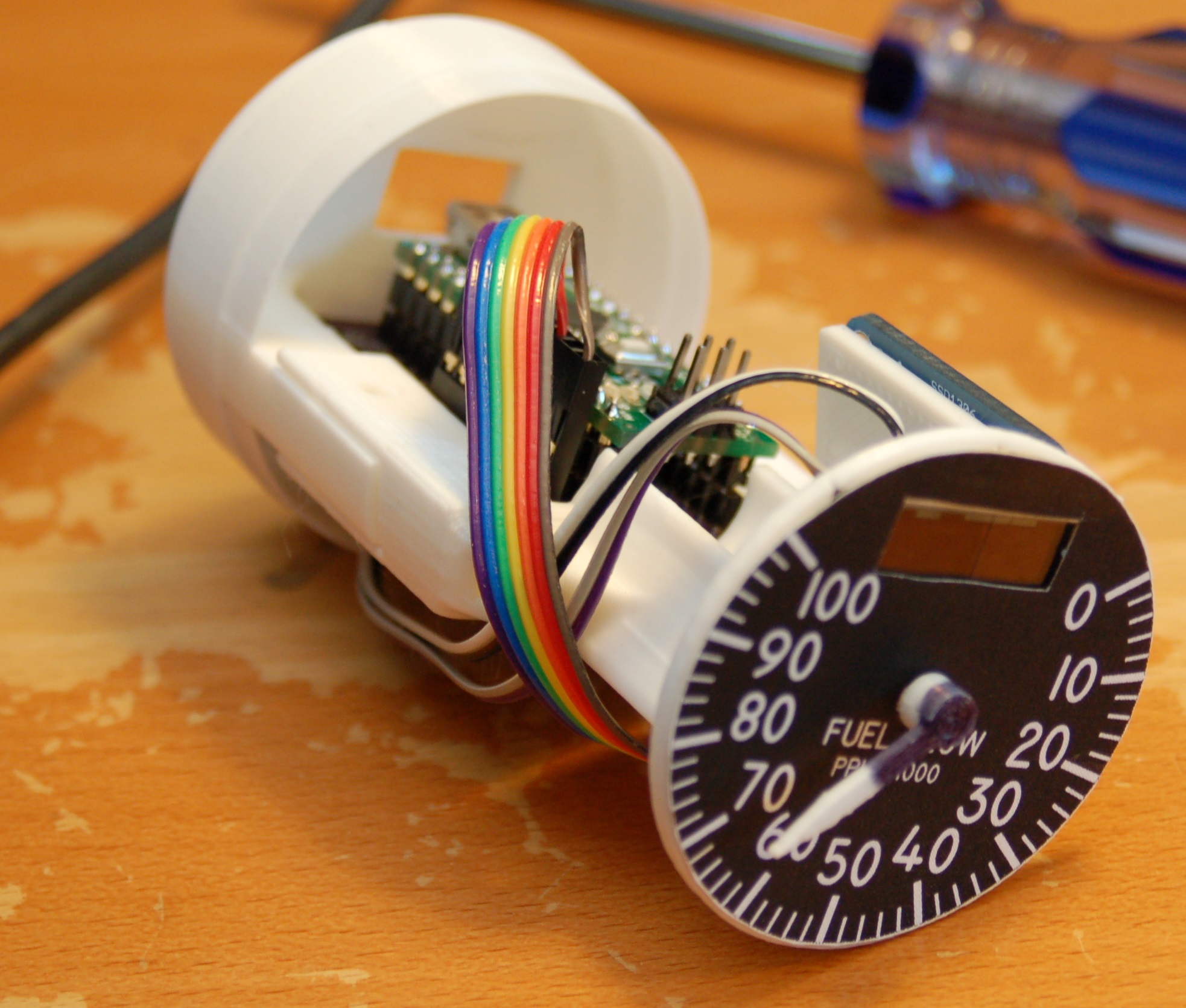
Here’s how it looks with the “test” case on it:
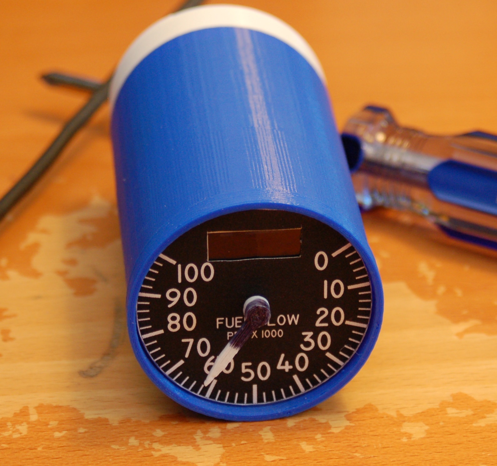
Finally, here’s a short video of the gauge in operation:
Once I have the time, a properly sized case will be printed (the blue one is too short) and I’ll get a good laser engraved face on the gauge.
It’s coming along! 🙂
[Here are the gauge electronic components, sans header connectors]