

I’ve recently been working on getting the six engine gauges for the F-15 put together. Since I’m not going to be using real instruments, I needed to scratch build them. Last year I did a short demo that shows how I’m using a small OLED display to emulate the “odometer” style display that’s used in the Fuel Flow, Temperature and RPM gauges. I finally got around to doing the software integration and did a short video that shows both the air core and the OLED display working together:
Some weeks later, the boards I ordered from Osh Park arrived and I got the first one soldered up.
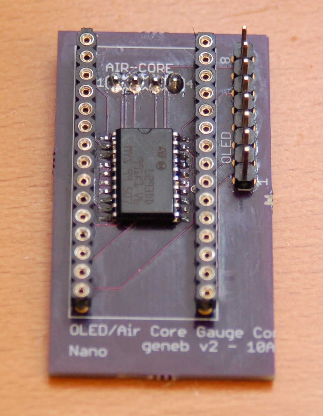
This is the top of the new interface board. The chip in the center is an LM293DD dual h-bridge chip. This is the surface mount version of the LM293D that I bread-boarded the circuit on. The header on the right goes to the OLED interface.
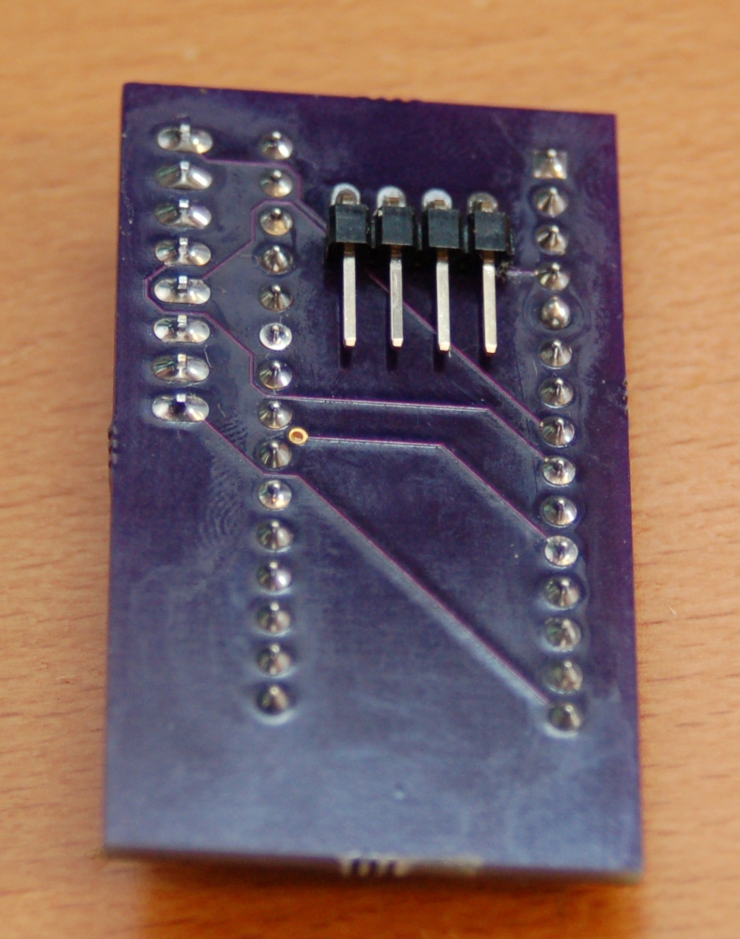
The bottom of the board has a four pin connector that will go to the air core motor.
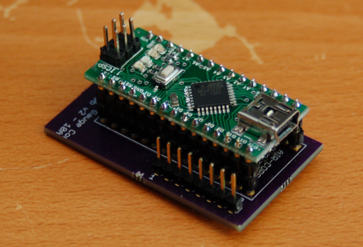
This is what the final assembly looks like after the Arduino Nano has been mounted.
The USB connector is at the back end of the board and will be accessed through an opening in the back of the instrument. I’m still working on the design for the instrument core, so I don’t have much else to show yet.
More soon!
Comments


Powered by WordPress | Copyright © 2026 F-15C Flight Simulator Project. | All Rights Reserved. | Design by Shea Media
Arno on 09.04.2015
Hello Gene,
when I saw your demo last year I was half afraid you were going to put these inside the original instruments, but I should have known you better. BTW, are you keeping those?? 😉
Congrats to your progress once again! Nice to see it working out (even though I am a great fan of all things electro-mechanical and an active, light-emitting display will always look wrong to me in such an instrument). I see that these displays are programmable to pixel level, are you adding a scrolling animation to capture the original odometer action (and maybe even indicate fractions of a digit) or will your values always change so swiftly that it wouldn’t be worth the trouble? Even then, introducing some vertical “blur” might look more natural than changing the digits in a flash. Just suggestions from my side, m’kay?
I might have some questions to ask on “synchro” stuff and aircraft Instrumentation in general in the near future for the “air-headed” project of adding some aero gauges to my Piaggio Ape 50 microcar a.k.a. the “Trash Transport Truck”. Will do so per private e-mail. Hey, Piaggio originally was an aircraft and aero engine company, so what!!
So Long, all the best,
Arno
admin on 09.04.2015
As hard as the originals were to find, yeah I’m keeping them. 🙂
At some point I plan on taking the time to write a pretty good odometer display emulator that will roll the digits properly. One issue I’m going to have is that the resolution isn’t high enough to make the digits “perfect”, but they’ll work. Ideally I’d use a color display as the far left digit has a red background when it comes into view. I do need to find out if the numbers “flick” when they change or they actually roll. Because I can’t open the gauges (and I’m not going to just cut ’em open), I can’t tell precisely how they operate.
Be aware that aircraft synchros require a 400Hz AC power and signal source. You may have a hard time finding that in a truck. 🙂
g.