

SFS box is done!
After a very, very long delay, the SFS box is finally finished. There’s literally nothing left that needs to be done for it. 🙂
From last weekend’s work, here’s the last two stages of wiring.
First, lace it up!
Then it gets cleaned up and attached to the interior of the SFS box.
I use a LOT of waxed lacing cord. It makes for a very nice looking wiring harness and doesn’t snag on everything like a nylon wire tie will.
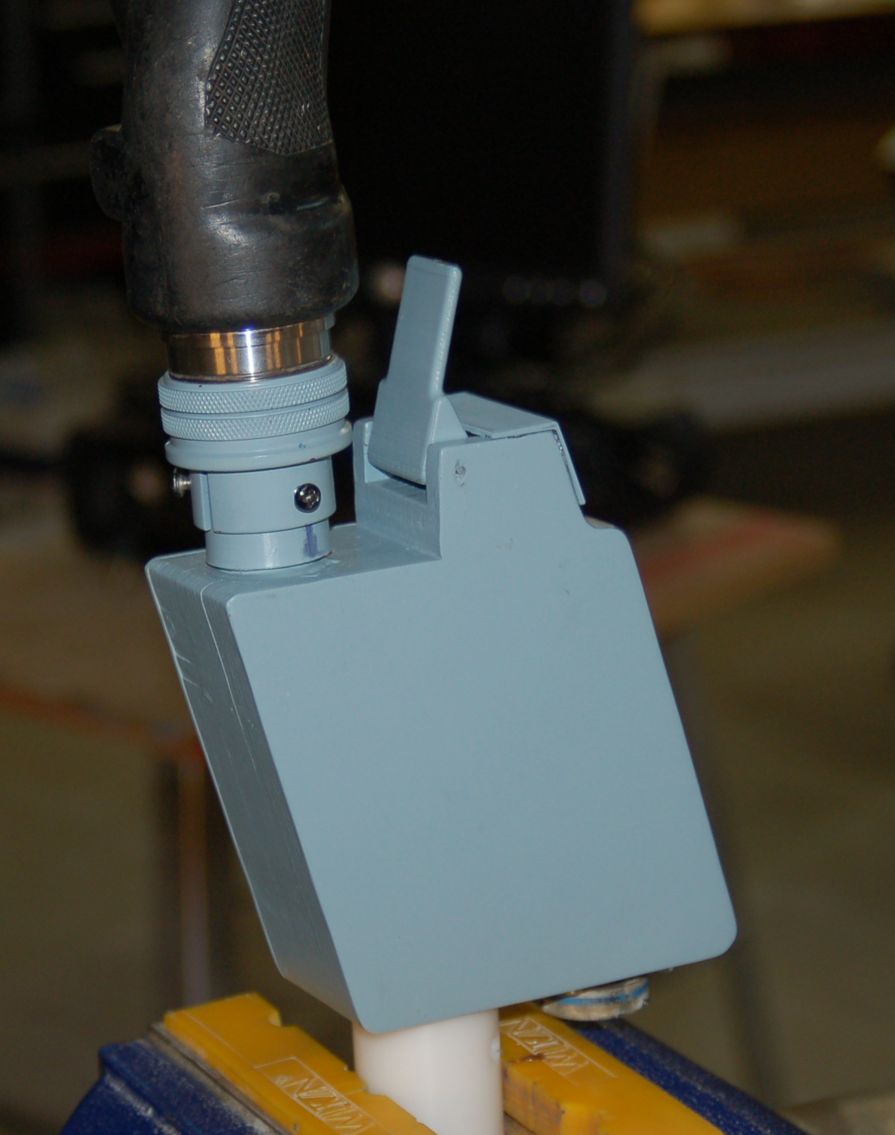
The next three photos show the completed SFS box with the grip attached.
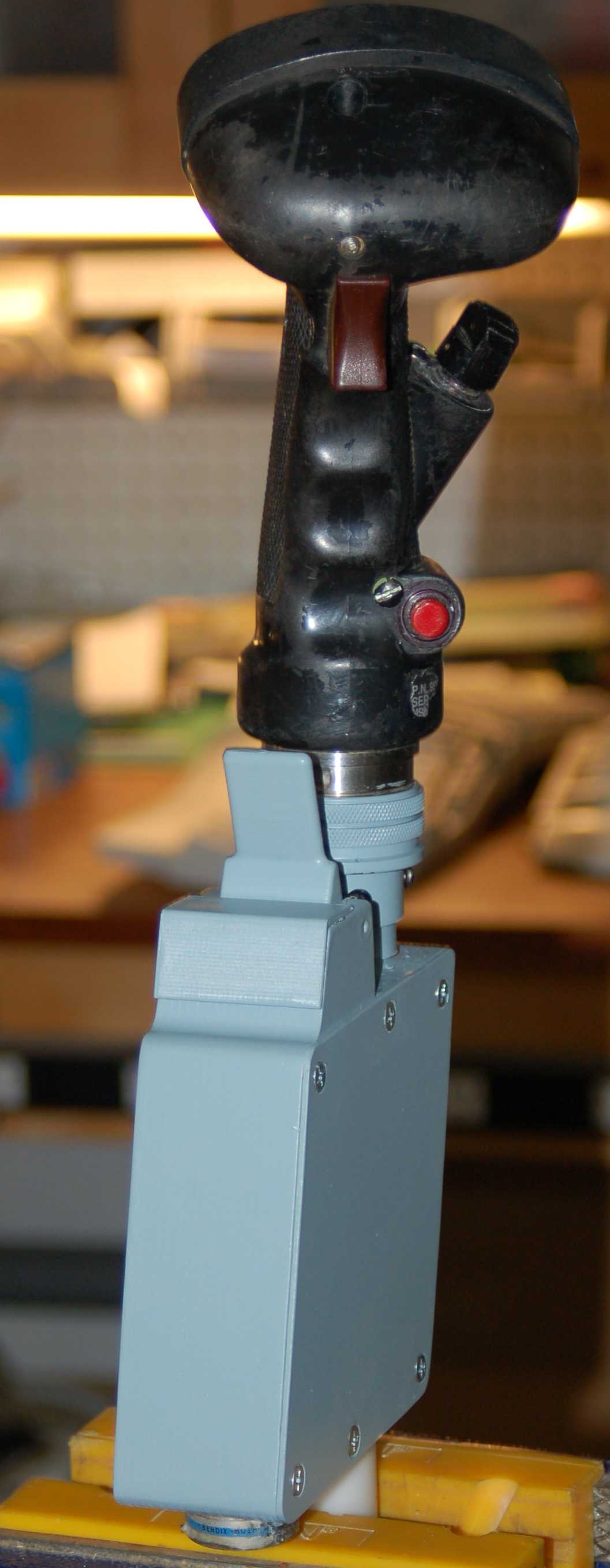
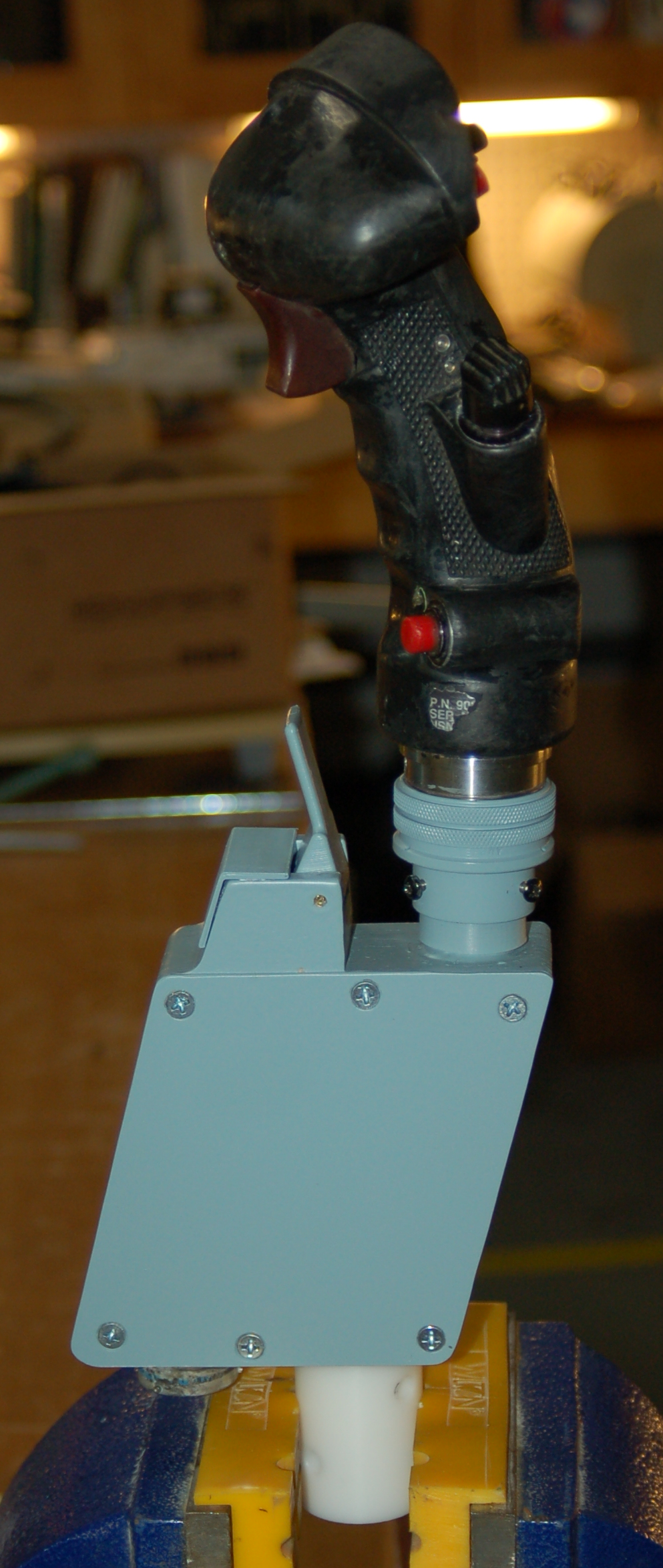
And finally, here’s what it looks like installed in the cockpit!
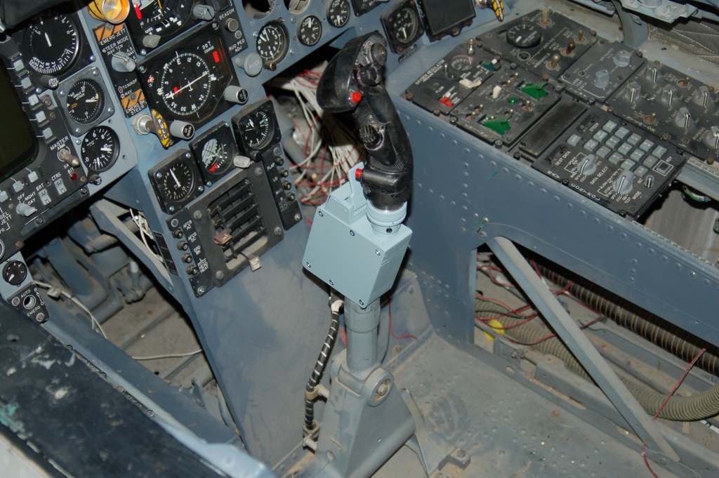
I really, really need to dust. 🙂
Throttle quadrant & SFS box work
This past weekend saw some renewed effort on the project. For the last 18 months I’ve been up to my neck in 3D printer things – I’ve been writing the assembly and user guides for SeeMeCNC’s line of excellent 3D printers. http://www.seemecnc.com
One of the things I got done was to finish the missing pawls for the throttle quadrant and get them installed. These pawls act as both an idle gate bar and as a trigger for the engine start switch. In order to pull back past the idle gate, you need to pull up on the finger lift. This prevents you from accidentally cutting fuel off to the selected engine when pulling the throttle fully aft. When starting the engines, you pull up a finger lift and the pawl activates a microswitch that in turn causes the JFS to link the AMAD to the selected engine.
Here’s the new pawls – the originals were sold unfortunately.
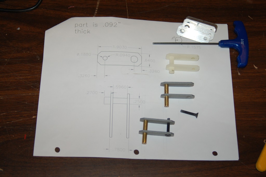
New throttle pawl parts & drawing
Here’s a photo of what the new parts look like installed:
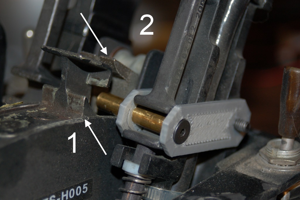
Pawl installed
#1 is the idle gate. When the pawl is forward of it, you can’t pull the throttle arm fully aft without lifting the pawl over it.
#2 is the engine start switch. When the pawl is aft of the idle gate, pulling up the finger lift will cause the pawl to engage the switch. The sides of the pawls are 3D printed from ABS plastic. I may replace those printed parts with machined aluminum before installation back in the cockpit.
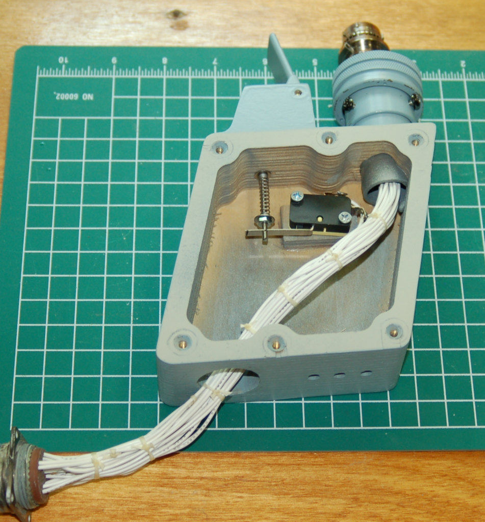
The other thing I got accomplished was the fitting out of the SFS box! That’s been a long drawn out project for sure! I got the Nosewheel Steering/AP Disconnect paddle & switch installed on Saturday and I completed the wiring & other assembly this evening.
Here’s the start of the process:
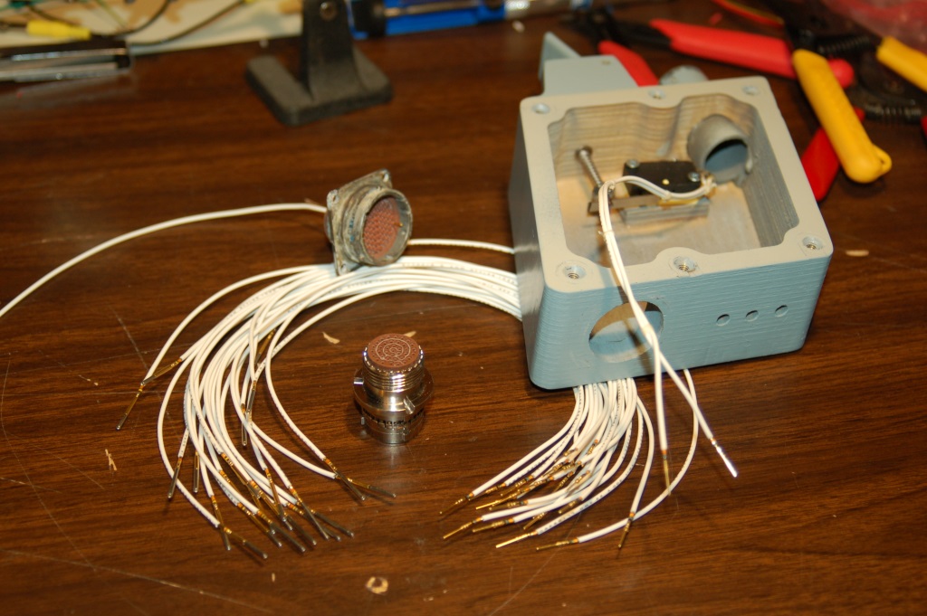
SFS wiring parts.
The Post-MSIP II grip I have uses 23 wires to cover the six switches on the grip. An additional two wires are needed for the NWS/AP Disc. paddle. The silver connector shown above is the female connector that the grip mates to and was a surplus item a friend scored for me. The very “used” looking connector behind it was the floor-mounted end of the SFS wiring harness that went from the cockpit floor up to the bottom of the SFS box. Since the connectors are insanely expensive (roughly $175 for this one), I decided to re-use existing connectors whenever I could. The other end of the SFS wiring harness will mate to this connector and while the floor connector will be different, it will be nearly impossible to tell it’s not original. This wiring job was a one-way task. I had inadvertently used 22ga wire instead of 24ga and didn’t realize it would be a problem until I’d put all the female crimp-on connectors in place. The pin removal tool I have is too small to fit the 22ga insulation properly, thus making the pin insertion a permanent deal. The pin & socket insertion process took about 20-30 minutes – I did NOT want to make a mistake that would either ruin a connector or cause me to have to cut and splice out a mistake. Fortunately, I got it right. I think. 🙂
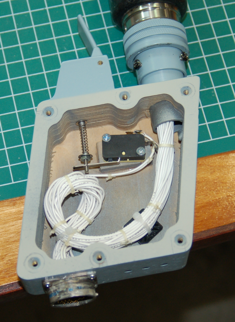
Here’s what the result looks like:
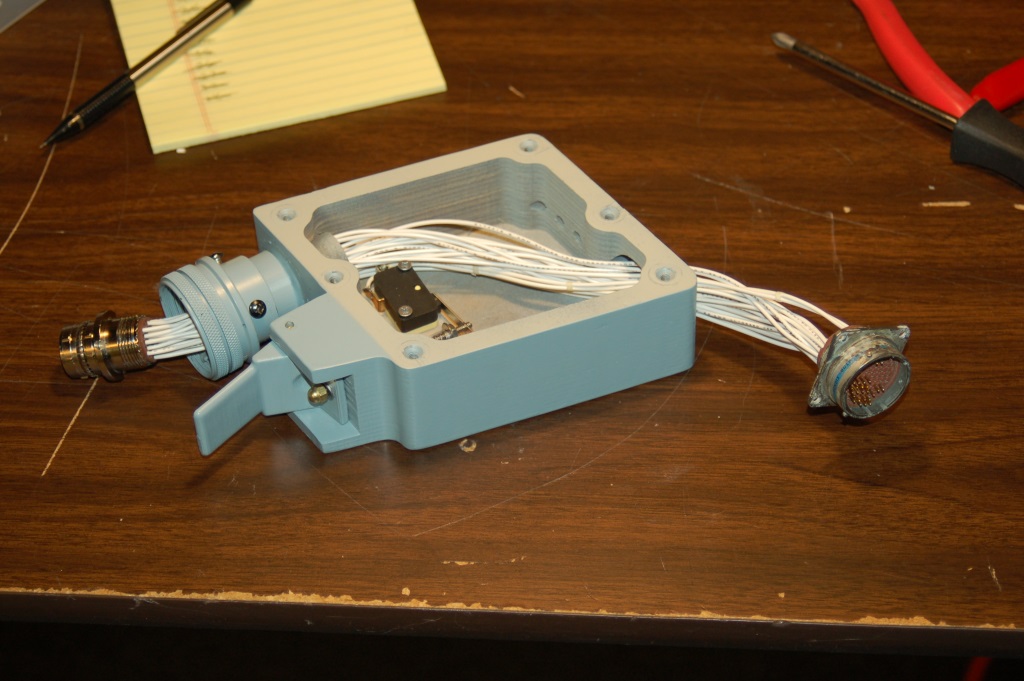
SFS nearly done!
All that remains is for the bottom connector to be screwed into place and then the wiring needs to be wrapped up in lacing tape and tied to the interior of the SFS box.
The final step will be to install the machined Delrin installation post I made a few years ago and get it properly drilled so I can bolt the SFS box to the lower stick assembly. That should be done this coming Saturday and I’m really, really looking forward to it!

