

First up, here’s what the new SFS interconnect cable looks like:
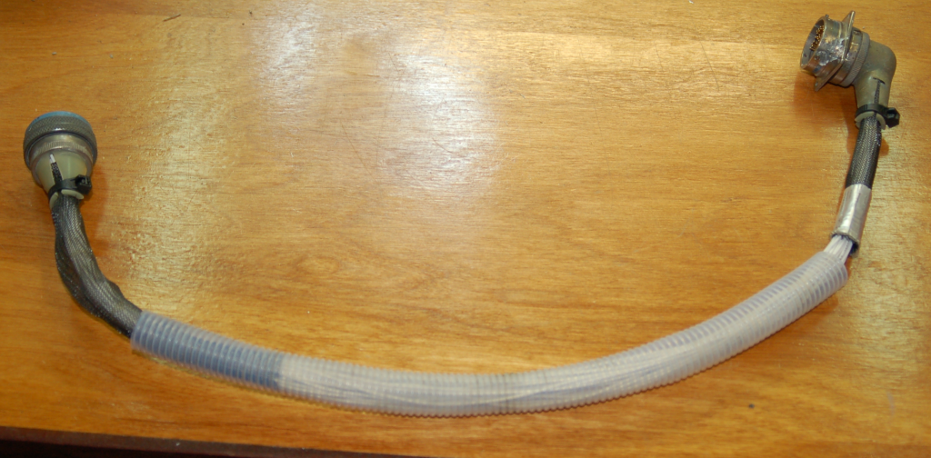
The end of the cable on the right is bolted to the cockpit floor and the other end winds its way along the pitch axis bearing and up the centerline of the roll axis section. It attaches to the bottom of the SFS box in order to bring the signals from the SFS box & grip to the control interface hardware that’s going to be installed in the left side equipment bay that’s under the cockpit. The clear plastic tube was part of the original SFS interconnect cable. I was able to salvage it for the new cable.
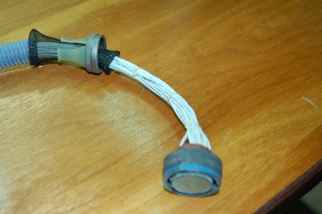
Above is a shot of the SFS end of the cable right before I closed up the outer sleeve.
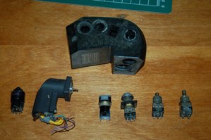
I’ve been working on getting the inboard throttle grip rebuilt. Having friends in interesting places helped out quite a bit with this part of the project. The F-15C inboard grip contains a “slew” control, which is essentially a tiny little force sensitive joystick. It’s used as the Target Designation Cursor controller. You can see it in the photo below, the “L” shaped object.
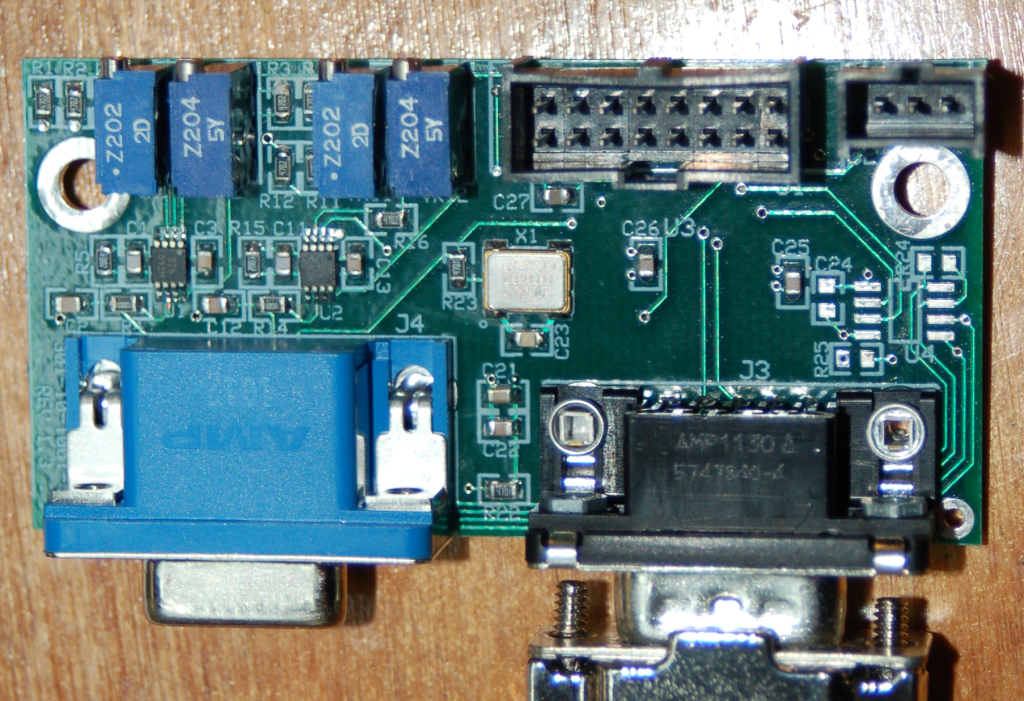
The slew control requires an input amplifier because the signal it puts out is very, very tiny. This is where my smart buddies come in. They make an interface board that is specifically designed to turn these slew controllers into joystick axes. The board supports the slew control as the main x/y axis and has a few other goodies on it that make for a complete joystick interface. Below is a pic of that board.
[31Aug15 Update!]
A few people have emailed me asking about more information on the slew control -specifically the pinout. Here you go!
Pin 1 – 5VDC
Pin 2 – X Axis
Pin 3 – Y Axis
Pin 4 – GND
I should also note that one the folks that emailed me was able to successfully get the slew control working by using the analog inputs on an Arduino!
My friends Rob & Bill have spent the past couple of Saturdays building frames to hold all the side console panels. These will be used to design and build the wiring harnesses for each side console.
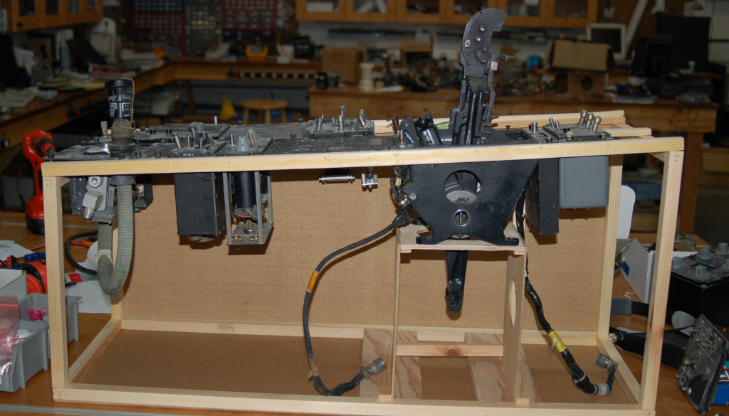
I’ll be adding tie points to allow me to properly build out the wiring harness. It will be a tedious project, but the end results will be more than worth it!
One of the more troublesome issues I’ve got is dealing with the six engine gauges. Each gauge uses a very tiny “odometer” style readout to supplement the needle. Up until recently I’ve been avoiding those gauges like the plague. I’ve only got one of each (RPM, FTIT and Fuel Flow) and I have no wiring diagrams to hook them up, even if I had digital to synchro converters.
A few weeks ago a user on the #sparkfun IRC channel pointed me to a tiny, tiny OLED display sold by Adafruit – http://www.adafruit.com/products/661
It turns out that this thing is just the right size to replace those odometer displays that the engine gauges use!
They’re attached to their driver board via a bit of double stick tape that’s easily removed. Once that was done I measured the display and created and printed a 3D model of a gauge face that would support the display, its driver board and a tiny air-core motor for the needle. Each instrument will be driven by an Arduino Nano that’s attached to a carrier board that will hold an L293D H-Bridge chip that’s required to drive the air-core motor. Each instrument will be mechanically identical with the exception of the gauge face. Makes ’em easy to build.
Here’s a shot showing test code running on the display and the real fuel flow indicator I based the face artwork on:

The “real” face will be laser engraved on some properly prepared 1/16″ acrylic. It should look great once finished!
Here’s a short video showing the test code running on the display: httpv://youtu.be/GwEPE_N-0qY
Next update I’ll try to show photos & video of it working all as one system. I’m waiting for some Arduino Nanos to show up – I’m using an Uno as the test platform right now.
Comments


Powered by WordPress | Copyright © 2026 F-15C Flight Simulator Project. | All Rights Reserved. | Design by Shea Media
Alexander Dragoset on 08.06.2014
Hi i saw your build log while searching the internet for some information on the throttle slew controller. I’m in the process of rebuilding an F-15 throttle grip myself for a home made throttle quadrant and was wondering if you had any information on wiring up the slew controller to a USB joystick controller. My specific controller is a BU0836X from http://www.leobodnar.com. I also purchased 2 bi directional load cell amplifiers in anticipation of the problem you mentioned of the slew controller only outputting very small signal voltages. My current question involves the 4 wires coming out of the back side of the slew controller. Mainly at least 2 of them are signal wires while the other 2 must supply the excitation voltage for the load cell. I may be totally off here as to how this little device functions as documentation is pretty hard to find and it seemed you would be the person to talk to as you have actually rebuilt one before. Anyway thank you for your time and the build log as it’s fairly interesting to see someone take on such a large and in depth project.
admin on 08.07.2014
Alexander, email me directly (geneb@deltasoft.com) and I’ll dig up my notes on how it’s connected. Keep in mind that I’m using an interface board that’s purpose built for the task, so a generic amp may not work.
g.