

Wow. It’s been a while since I’ve posted an update! Since the last update, I’ve nearly finished the re-wire job for the right side console. I was fortunate enough to get a pile of brand new canon plugs and matching pins. This is allowing me to re-wire the cockpit using the original bulkhead connections, which makes for a much neater build! In order to build the wiring harness, I’ve had to build it out panel by panel. With the completion of the TEWS panel, the wiring harness will be completed. The only thing missing will be the CMD panel that controls how the chaff & flare dispensers behave. I’ve never been able to get a photo of that panel, so I’m going to hold off until I do and can make a new one from scratch.
The navigation control panel is going to be a stand-alone, USB interfaced device due to its complexity. That should be an interesting rebuild.
I started the TEWS panel rebuild nearly 3 years ago, which is kind of embarrassing. In my defense, I DO have a lot going on. There’s good reasons it’s been 15 years since this project started. 🙂
When I first wrote about the TEWS panel, I pointed out that I needed to replace the two destroyed Korry “FAIL” indicators that the panel had. I decided to go a different route than the Korry replacement I built for the IFF panel.
For the 1″ FAIL indicators, I 3D printed a new indicator shell and had some small circuit boards made up. The boards hold 5 1206 sized amber LEDs and a 1206 sized 56ohm resistor. This allows me to power the indicator at 12v. I’d never worked with surface mount parts before, but this turned out pretty nice.
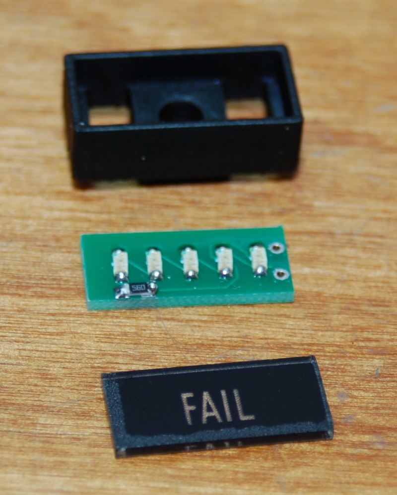 I had originally used a special Rowmark plastic to do the faceplate for the indicator, but I really didn’t like the result I got. I shot some 1/16″ clear acrylic with flat black on one side and then reverse engraved it and cut it out on the Epilog. The down side of this is that you can see cutting artifacts along the edge of the faceplate. If I need more of this type, I’ll cut them first, then paint & engrave in a separate operation. That’ll eliminate the cutting artifacts.
The shell of the indicator is PLA plastic that I painted with flat black. It’s designed to accept a #6-32 heat set insert in the back in order to give it a mounting point.
Those heat set inserts are really handy to have around! They make building things with 3D printers a lot easier.
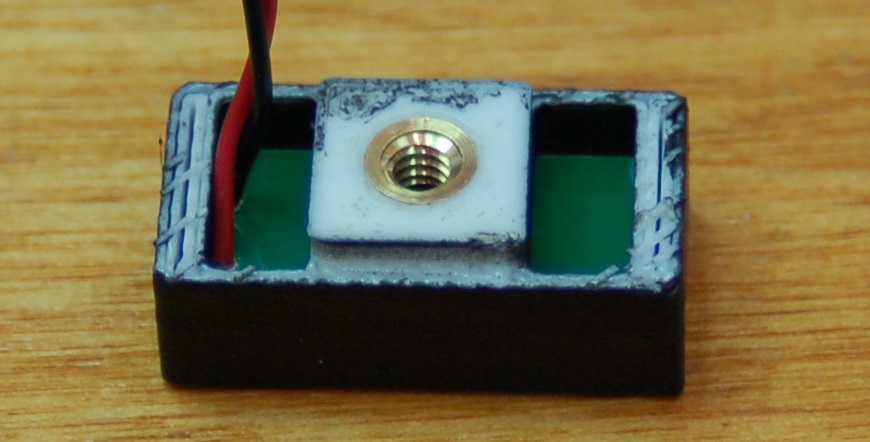
Heat set insert.
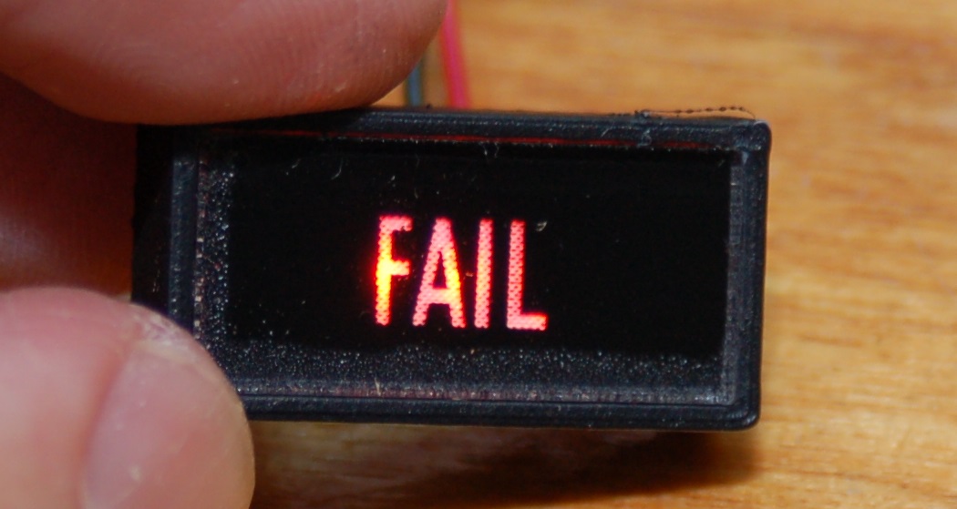
Here’s what it looks like powered up:
…and all three completed:
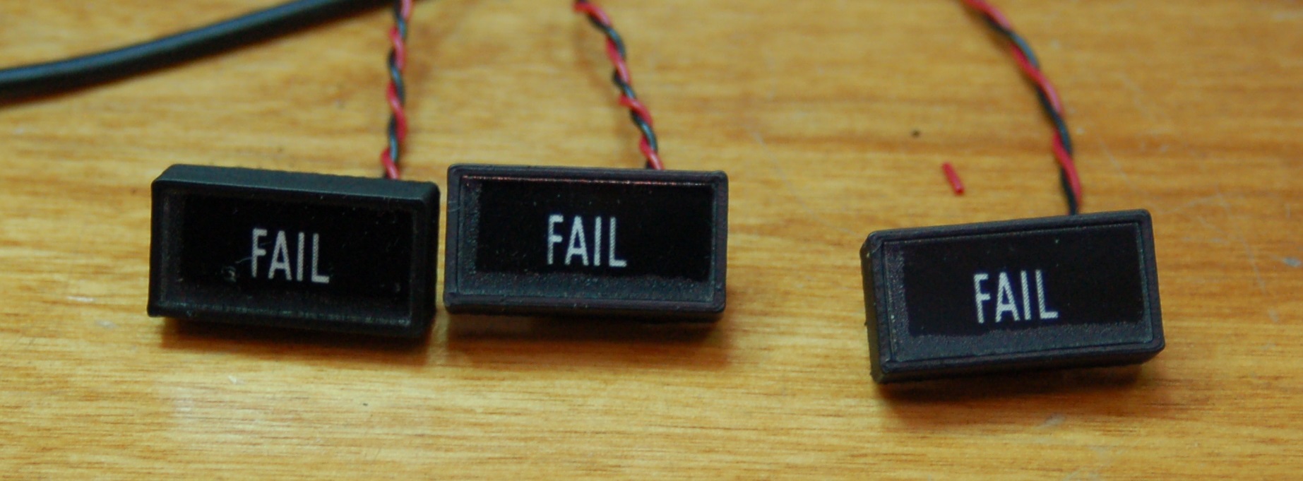
You can easily see the artifacts left from the laser cutting process…unfortunately. But hey, they work great.
The first stage of the rebuild was to get the cannon plug on the chassis removed and all the wires removed from it. Normally I don’t do this – I’ll make a map of what pin goes to what switch or indicator and go from there. The TEWS panel had a few problems – the 3 FAIL indicators needed to be replaced, there were two wrecked switches and there was a relay board that needed to go. This meant that it was simply easier to pull it all apart and start from scratch.
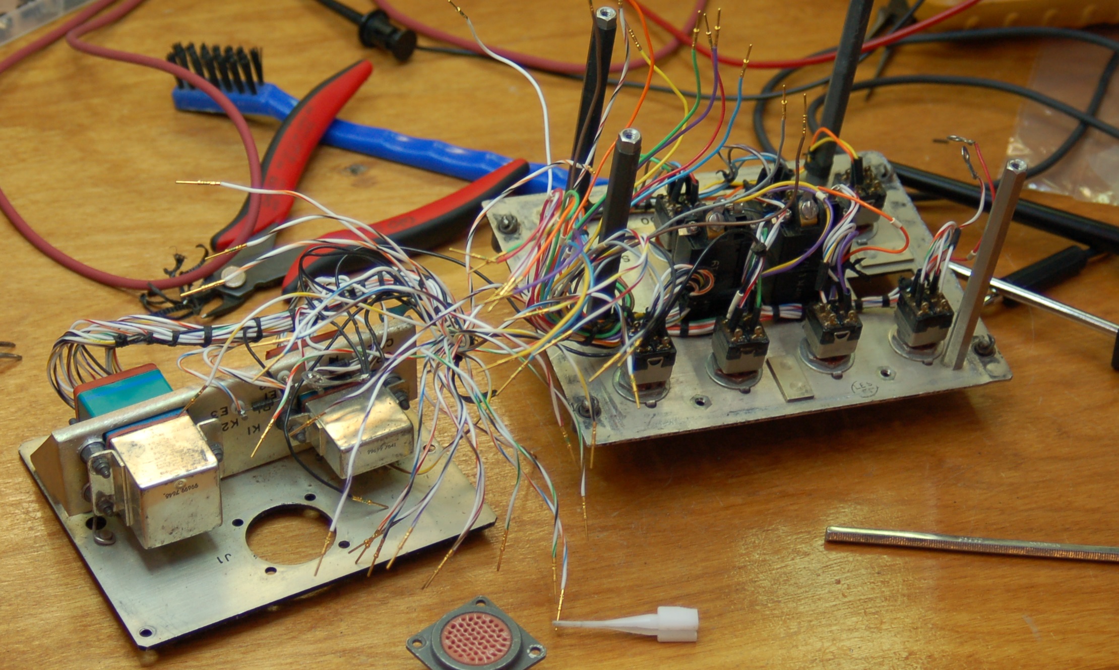
Pulled apart.
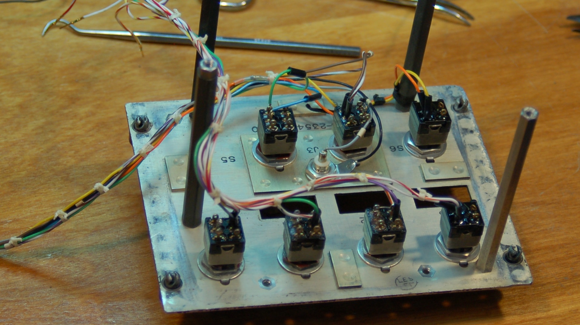
This is what the panel looked like after the two switches were replaced. The next step is to install the replacement Korry lights. As you can see, I’m still a huge fan of using waxed lacing tape instead of using wire ties.
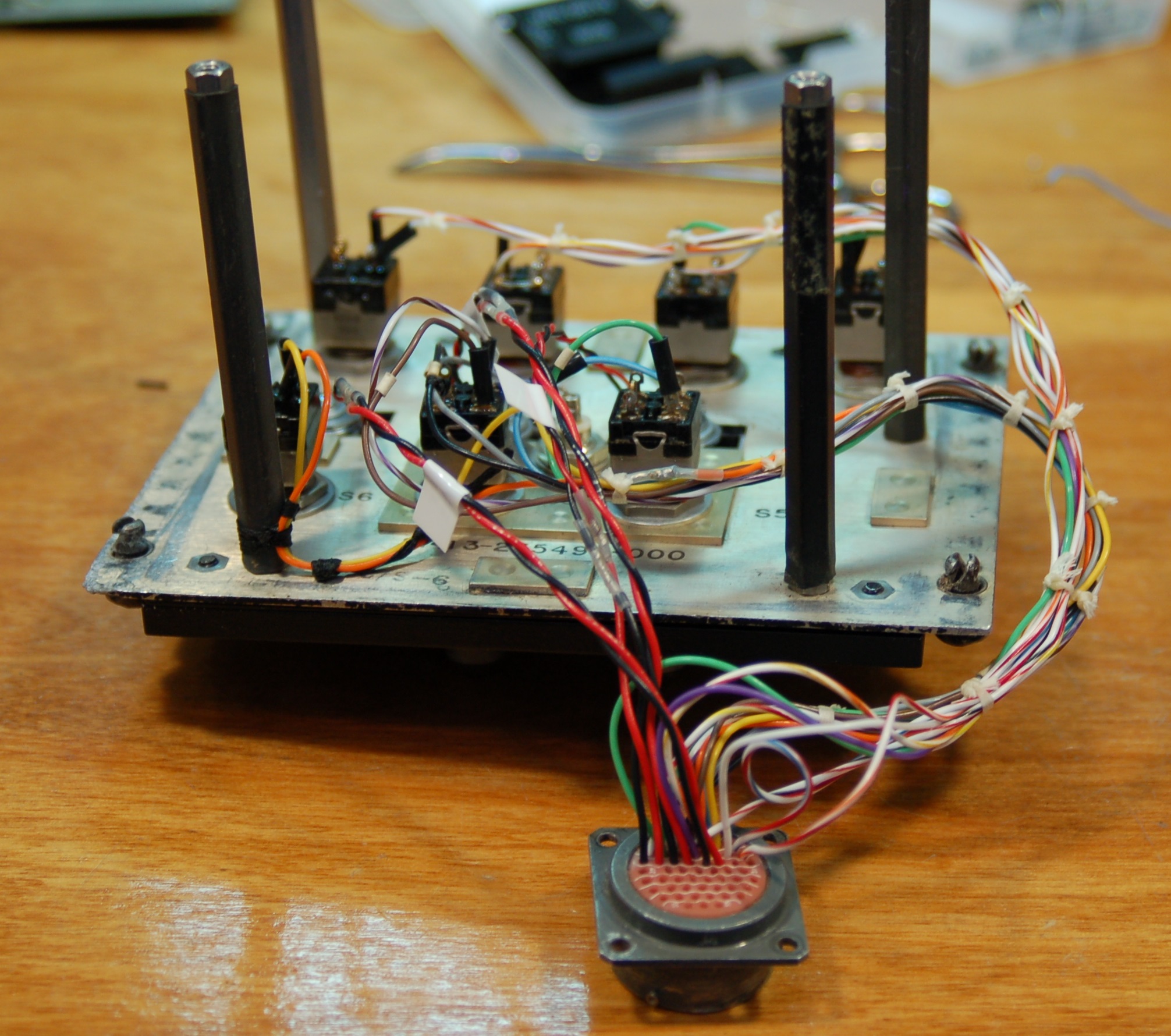
Unfortunately, I don’t have a good pic of the new Korry installation. The next step is to re-pin the cannon plug so things can go back together. The cannon plug gets re-mounted to the panel back and the new edge-lit panel is installed.
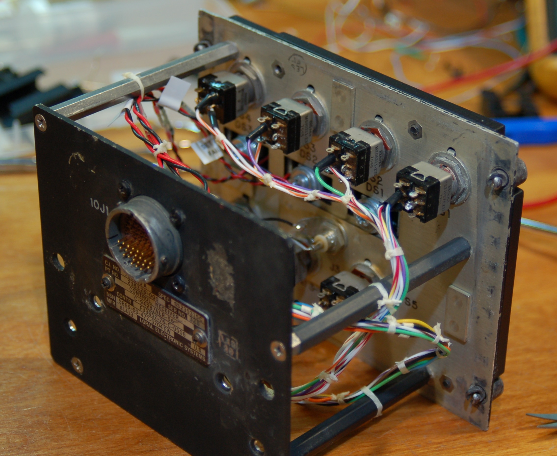
Here’s the newly rebuilt TEWS panel:
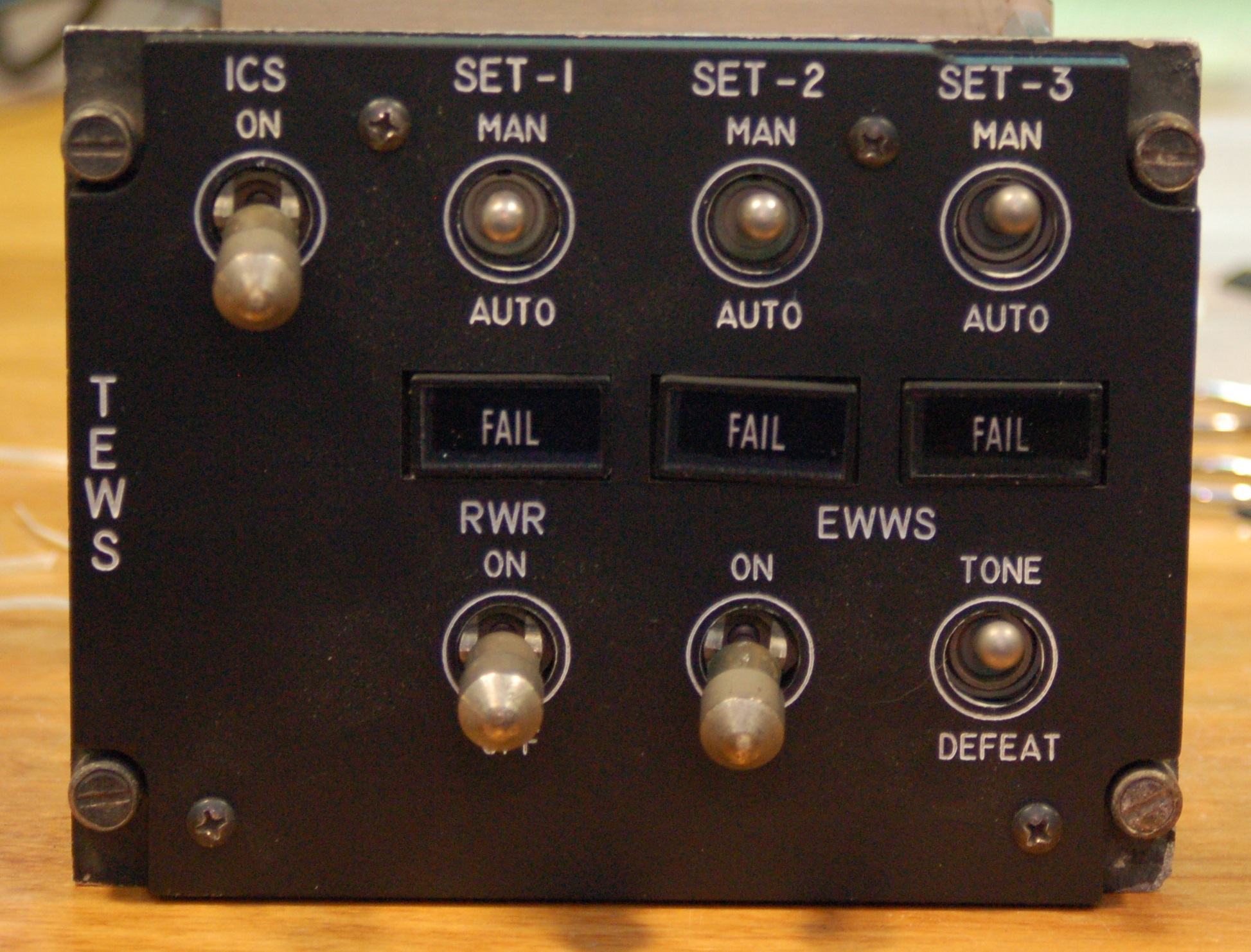
Done!
I also took a photo of the original edge-lit panel along with the only remaining undamaged Korry indicator along side the new panel.
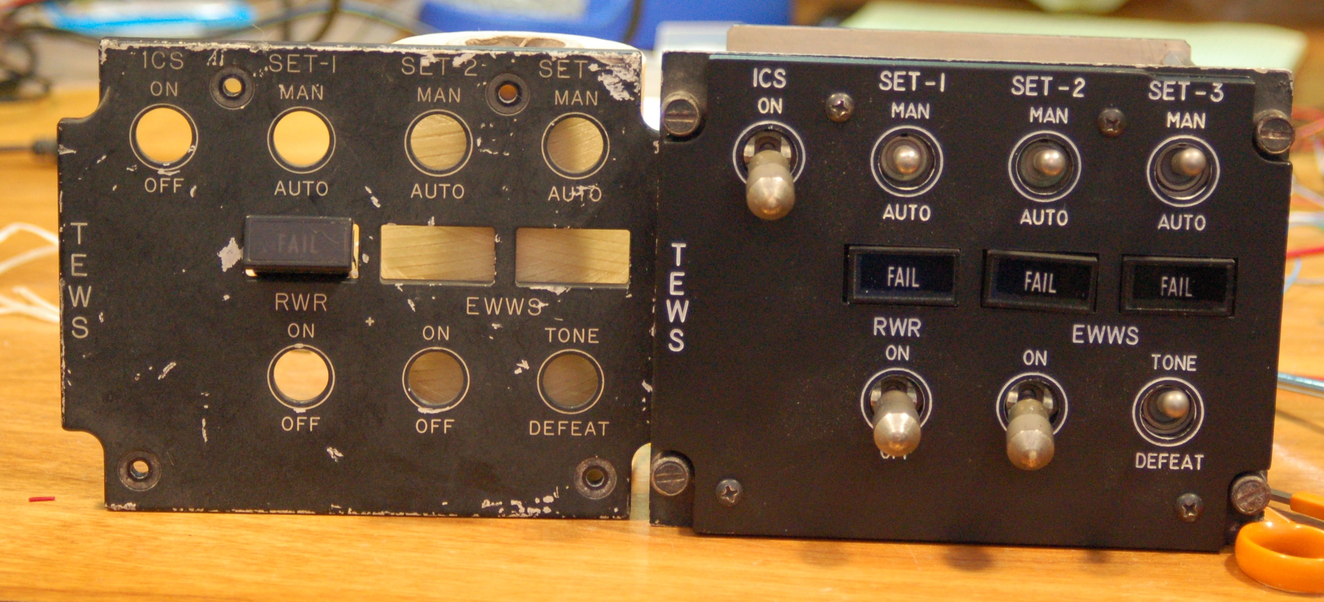
Before and after.
So what’s next… Well the first thing I need to do is finish de-pinning the female cannon plug that mates to this TEWS panel in order for me to make a new wiring harness for it and hook it up to the main 125 pin cannon plug that interfaces the right side console.
After that’s done I want to get the harness installed into the cockpit. From there I may hop either to the flight control re-interface and then to the left side console, or the console first and the flight controls second. I may also spend some time building the wiring harness needed to route the 55 pin cable from the Master Caution Panel to the forward bulkhead in preparation for connecting it up to the high power output boards I designed a few years ago.
Until next time (whenever THAT will be!), thanks for taking the time to stop by and read up on my latest nonsense. 🙂
Comments


Powered by WordPress | Copyright © 2026 F-15C Flight Simulator Project. | All Rights Reserved. | Design by Shea Media
Johan G on 09.18.2015
It is kind of ironic to see the FAIL indicators successfully light up. 😛
Jokes aside, it is nice to see that while the work visible in the blog may be going in a slow pace it is still going. Keep it going. 😀
Greetings from Sweden.
admin on 09.18.2015
Thanks. The new gauge turned out pretty well too. 🙂
g.
Sven Ruedel on 07.07.2016
Hello,
really overwhelming project. One of the best I’ve ever seen. Had to lough, as I read about the 15 years. Same here, started in 1998, build the first prototype the same year and then…
Now I’m back at my universal fighter & attack helo project. Your pics of the F-15 panel layout helped me alot.
Thank’s very much
Sven