

I don’t know if this update qualifies as a “milestone” or not, but I finally finished and installed the wiring harness for the right side console!
The adventure started this morning with the construction of the wiring harness for the recently finished TEWS panel. This consisted of cutting, stripping and adding pins & sockets to the 22 wires that are used by the TEWS panel.
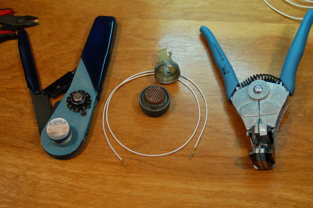
Weapons of choice…
The sockets & pins I use for the cannon plug that mates to the TEWS panel requires a special crimping tool. That tool is shown above on the left. It has a special die inside it that will apply a crimp to the pin or socket from four different directions. It makes for an excellent connection! The cannon plug, its shield and one of the wires is also shown above. The other tool is a new wire stripper I got – it’s made by Ideal and does a very good job in getting consistent strips – the pockets in the pins & sockets I use require an exact length – too short and it won’t crimp properly. Too long and you’ve got exposed wire at the base of the pin or socket.
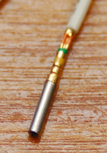
Crimped socket.
The photo above shows what a crimped socket looks like. You can see one of the dimples from the crimping die in the end that’s closest to the white insulation.
Assembly Stages:
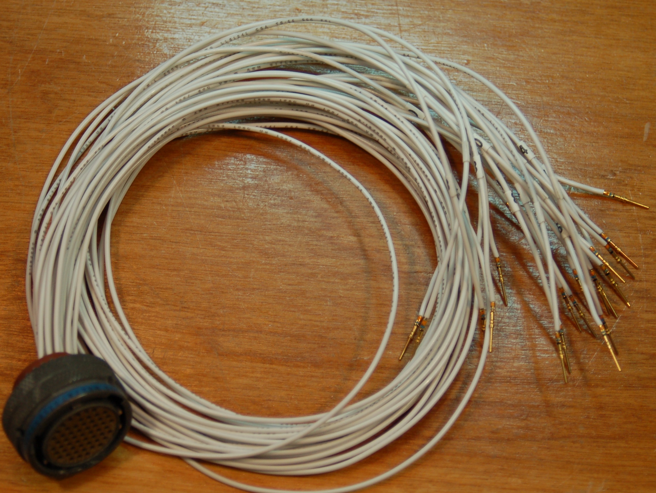
I kept all the “tails” from the wiring harnesses in the F-15 when I originally started working on it and cleaning it up. This allows me to use original connectors and labeling whenever possible. When I rebuild a panel, the last task is to break down the “tail” for that panel and re-build it using new parts where necessary and new wire. First I carefully take any sleeving or wrapping off the original as I can re-use that in the reconstruction. I then carefully de-pin the cannon plug. I keep the sockets I remove as they may come in handy later down the road. I’ll then clean up the cannon plug and the strain relief shell and set them aside until needed.
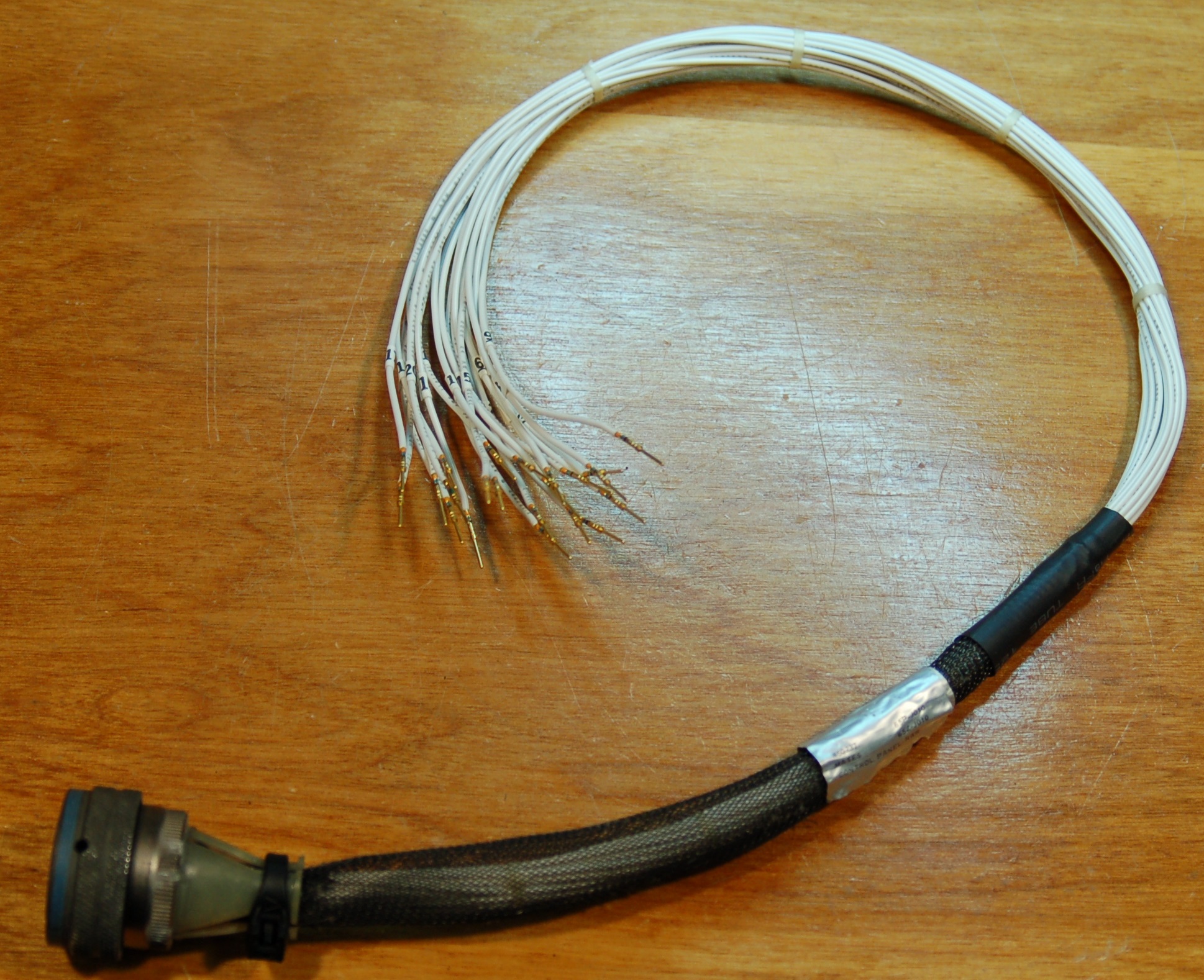
I then measure, cut, strip & crimp the new wiring. Each new wire gets a small number tag on it. This is important so I can know which wire goes where in the big cannon plug that is mounted to the floor in the F-15. After all the wires are inserted into the cannon plug, I tie the wiring up using waxed lacing cord. Then, the original sleeve goes back on the harness along with the strain relief shell and the original metal ID tag for the harness. That’s what is shown in the photo on the far right above.
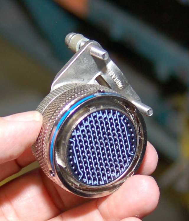
Now all those numbered wires get inserted into the 128 pin cannon plug.
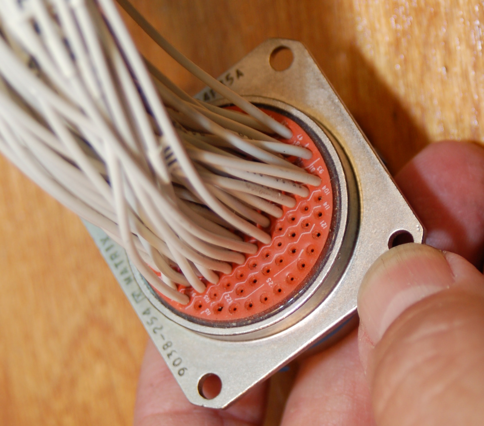
Back face.
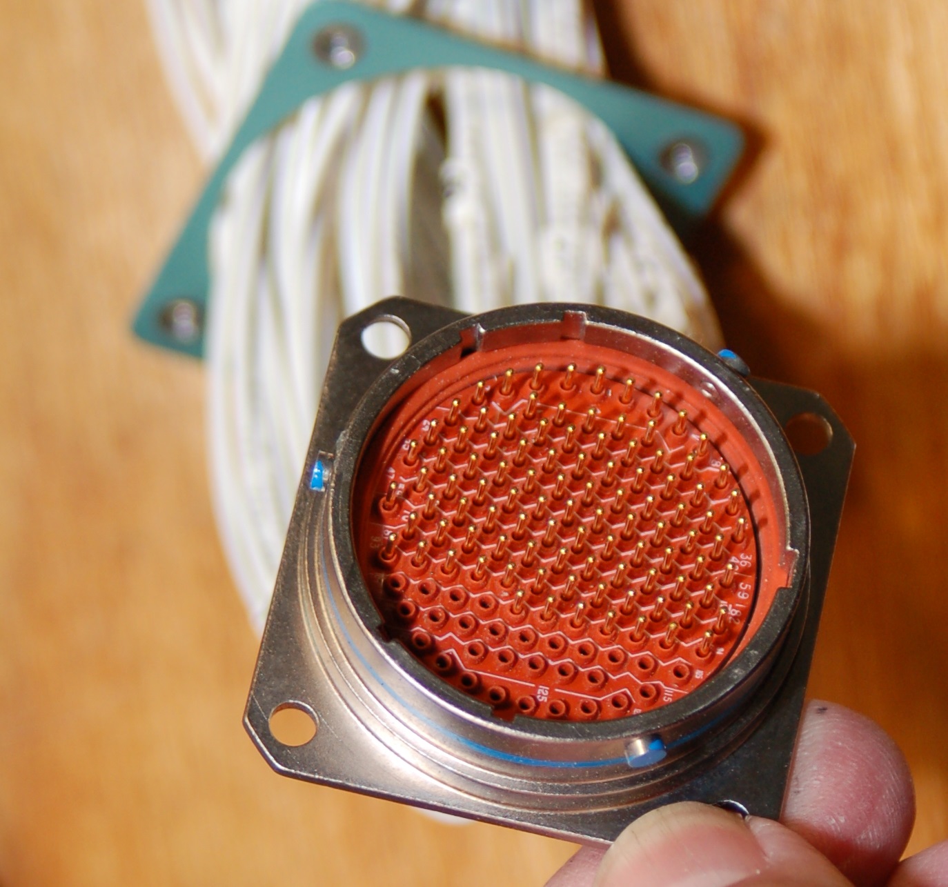
Front face.
The green part you see in the “Front face” photo is a nut plate. Each corner has a #6-32 nut that’s press-fit into the green ring.
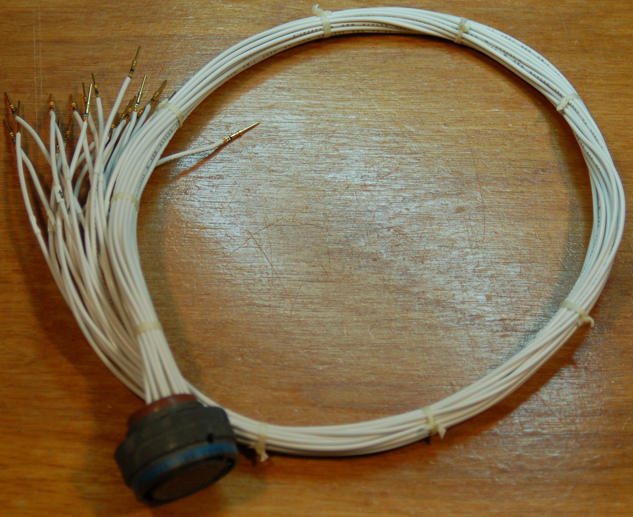
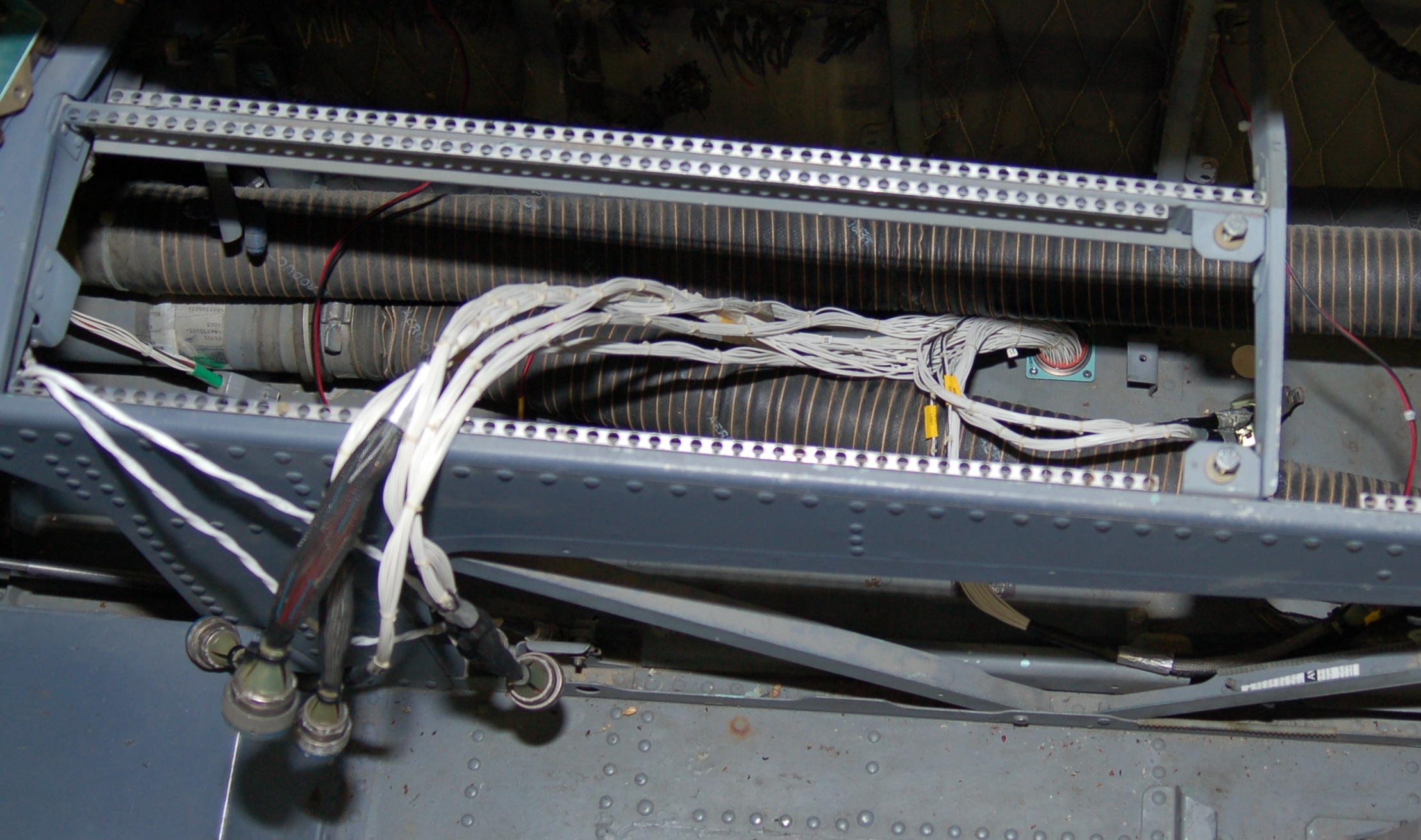
Here’s what the finished wiring harness looks like:
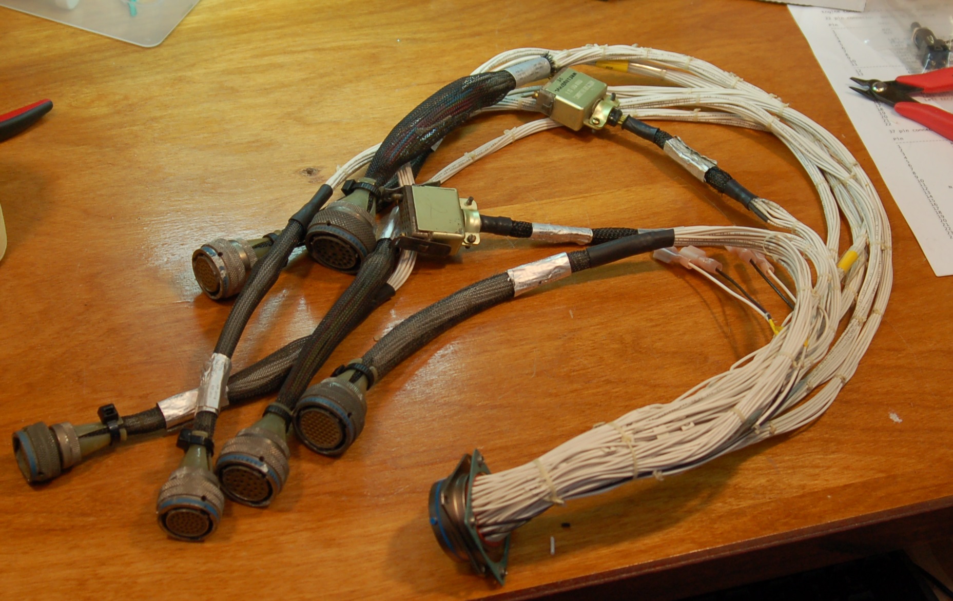
Done!
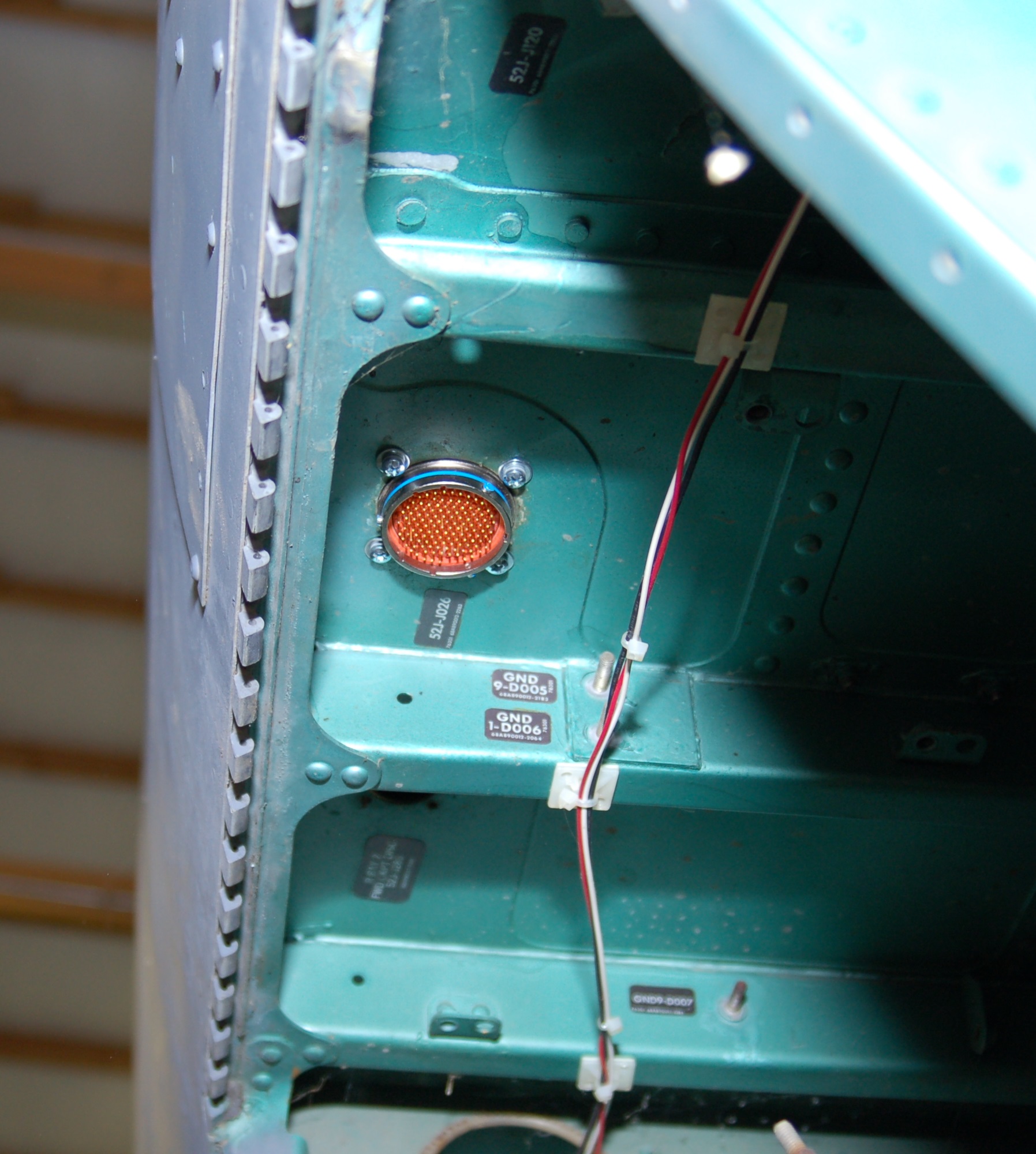
After much banging my head and cursing, I finally got the harness installed! It wasn’t easy as Rob wasn’t here today so I had to get creative in order to keep the nut plate in the right spot while I threaded screws in from the bottom.
Here’s what it looks like from underneath:
The space is pretty tight where the connector passes through the floor, so the wiring will have to make a 90 degree bend inward towards the centerline of the cockpit. For that, I’ll use a 90 degree strain relief on the 128 pin cannon plug that mates to the one on the right side console wiring harness.
I also managed to get the wiring harness that connects the SFS box & flight grip to the cockpit floor. You’ll recall in a prior update that I’d rebuilt the original as part of the new SFS box build process.
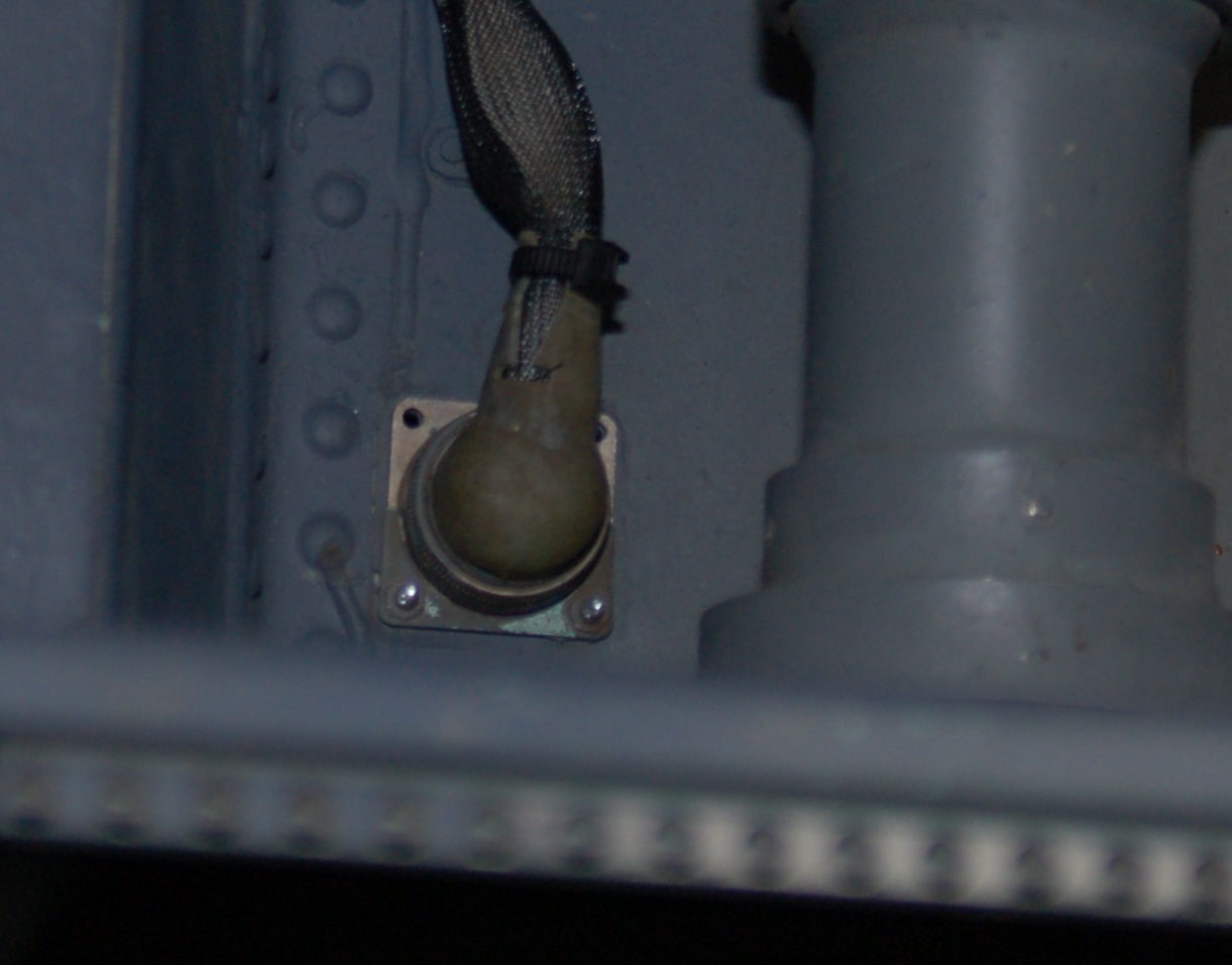
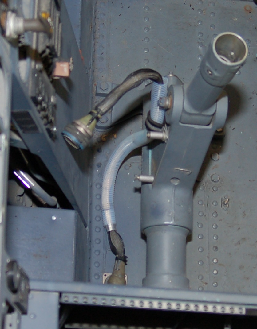
Floor passthrough.
Unfortunately, when I did the rebuild of the SFS box harness, I completely forgot about the nutplate that needed to be present. That resulted in me having to cut the old one in half so it could be installed afterwards. Unfortunately, I seem to have lost the other half, so only two screws are holding it in place right now. As soon as I find the other half I’ll get it installed.
Here’s what it looks installed:
I’ve only got one of the two wire clamps installed, but I’ll get that done at a later date – I’ve managed to misplace the 2nd one. 🙂
Thanks for reading!
Comments


Powered by WordPress | Copyright © 2026 F-15C Flight Simulator Project. | All Rights Reserved. | Design by Shea Media
Kirk on 07.29.2015
Haven’t dropped in for a while but am delighted to see that this epic project is still forging ahead. Arguably the most inspirational simpit on the web.
Keep up the good work!!
admin on 07.29.2015
Thanks Kirk! Hopefully progress will speed up a bit….but I’m not holding my breath. 🙂
Kirk on 08.06.2015
Better to do it right than quickly! 😀
It’s the quality of workmanship and your attention to detail that so inspires.
Incidentally, do you happen to know if the SFS is common to the F/A18 or AV-8B? The SFS box looks (superficially) quite similar in dimensions to the grip connection on the Harrier II but I’m not aware that the control system incorporates force sensing (there is a system that limits roll travel above a preset airspeed but the mechanism for this sits much lower down on the control column.).
Cheers,
Kirk
admin on 08.06.2015
I don’t know anything about the Harrier, sorry. The F/A-18 most likely DOES have an SFS box since it’s a contemporary of the F-15 design and likely has a similar hydro-mechanical system. Keep in mind that SFS stands for Stick Force Sensor. At the base of the cannon plug that fits the grip is a load beam. It operates very similarly to how the force transducer in the stick base of the F-16 works. In the F-15, you can pin the stick between your knees and fly the jet by applying force to just the grip. Conversely, if you flip off the CAS, it disables the force sensor and from what I’ve been told, “flies like a Cadillac with four flat tires”. 🙂
Peter Gottlieb on 11.27.2021
Long shot here, I was wondering if you had any leads on where I might go looking for a control panel for the ASN-109 INS system. This is the unit that was used in the earlier F-15s, with designation C-8849/ASN-109. It says NAV CONTROL on it and it is to the right of the pilot. I have the actual IMU for this and have spent hundreds of hours reverse engineering it in an effort to get it running on my bench. I am at the point where I can power it up, get the gyro platform to erect, and see some analog outputs but could really use the control head. Despite this thing being obsolete for decades, zero information is available. Any leads at all would be really appreciated!
admin on 11.27.2021
Ooof. Yeah, that’s going to be a hard one to find. The one I have is the panel & displays only, no guts from the enclosure. I would keep an active search going on eBay,although “nav control” is a bit broad and you’ll end up with lots of car junk until you refine the search by excluding things (ex. “-car” eliminates any result with “car” in the title). Good luck!
g.