

This flight simulator involves a number of different power supplies that are used to supply the panel and instrument lighting (5VDC), various indicator lamps (24VDC), the control loading system (24VDC), and the CANBus I/O interfaces and instrument controllers (12VDC). For safety and operational reasons, there’s a need to be able to control what power supply comes online and when. For example, if there isn’t at least one engine running, you don’t need any panel or instrument lighting, and the control loader shouldn’t be powered up unless the simulator software itself is running.
The the most direct solution to the problem would be to have these various power supplies controlled by a switch panel somewhere. But c’mon, you guys know me. Where’s the fun in that?
I wanted to be able to have a set of power supplies under computer control and I wanted to use things I had on hand for the most part. Since I have a number of Raspberry Pi computers laying around, that was an obvious choice. I just needed to come up with some relays and a simple method of connecting the relays to the Pi.
For the relays, I grabbed the ubiquitous 8 channel relay board that is popular with the Arduino community.
The module shown above is representative of the units I bought. They can be had for less than $10 from Amazon, Sainsmart, and other vendors. These feature relays that have coils that operate at 5VDC and can handle roughly 10A per relay, which is plenty of capacity for the loads they’ll be handling.
The other bit of hardware I needed was a simple way of connecting the 8 control wires from the relay board to the Pi. For that I got a “hat” that was filled with compression terminals.
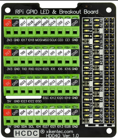
Like the relay panel, this can be found on Amazon and other retailers that stock accessories for the Raspberry Pi. I think I paid around $20 each for the ones I purchased from Amazon. This model is nice in that there are status LEDs tied to the GPIO pins on the right. It helps identify what pin is high/low.
One thing to note about the 8 channel relay boards is that they’re “active low” interfaces. This means that when one of the control lines is tied to ground, the relay will activate. This means that when you want to activate a specific relay, you need to set the connected GPIO pin to the LOW state. The potential problem here is what state the GPIO pins are in when the Pi is powered up.
If the GPIO pins are all set to a LOW state on power up, that means all the relays are going to close as soon as the Pi gets power or boots, depending on when the GPIO pins get initialized. I know that I could initialize the GPIO pins to a HIGH state (relays off) after boot, but that could be precious seconds where the power supplies are all on when they should not be.
There’s a mechanism in the Raspberry Pi that will allow you to configure the GPIO pins at startup, however the process that handles the GPIO configuration takes time to run. The Raspberry Pi wiki states:
“Note also that there is a delay of a few seconds between power being applied and the changes taking effect – longer if booting over the network or from a USB mass storage device.”
Normally this would be a problem, but the Raspberry Pi GPIO pins appear to come up in a “floating” state where the GPIO pin voltage is floating somewhere between the LOW and HIGH states. In my case, this is a good thing because the relay boards I’m using don’t respond to this “floating” pin state. This gives me plenty of time to safely force the GPIO pin states to HIGH during boot via entries in /boot/firmware/config.txt
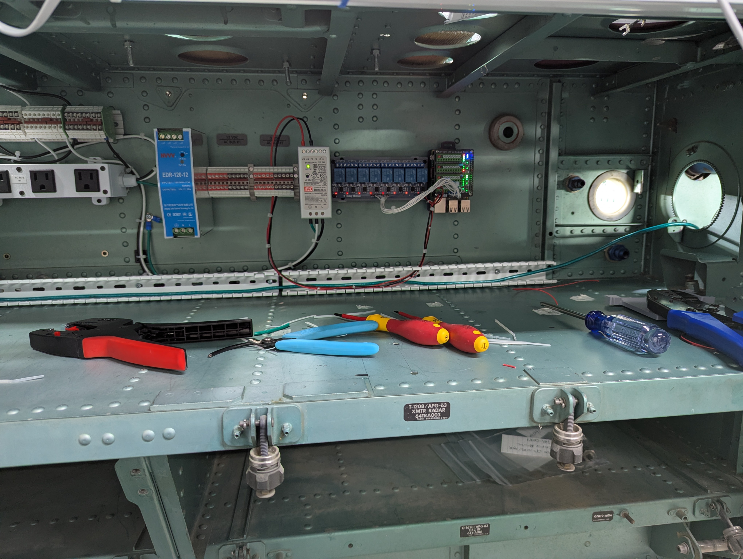
I’ve really taken to using DIN rail as my go-to mounting solution for the AC bus and DC power supply components because it keeps things neat and works very well. The photo above shows the state of the power supply controller as it was a few months ago. The power supply in the middle is a Meanwell 5VDC supply that comes up with the #1 AC bus. This feeds power to both the Pi and the relay board.
The power supply on the left is a 12V supply that the port side CANBus I/O control interfaces will need. There will be other power supplies installed – primarily for 24V indicator lamps & the storm floods, as well as one or more 5V power supplies per side for the side console and instrument lighting.
One of the advantages to using a single-board computer like the Raspberry Pi is the ability to use it as a web server. In this case, I’m using it to host a Blazor application written in C# that is used via browser to control the power supplies in the cockpit:
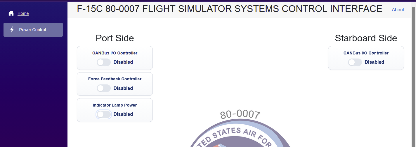
I’ll likely set up another Raspberry Pi connected to a touch screen that will automatically connect to the web interface on boot.
Currently, the power supply controller setup looks like this:
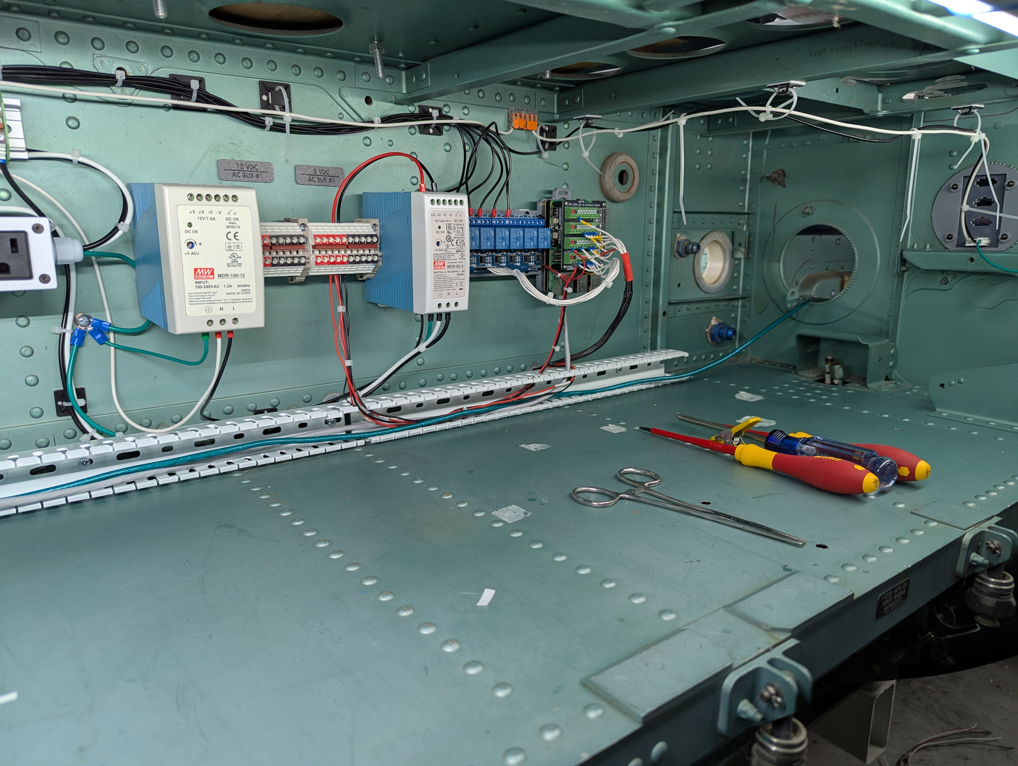
This shows what is likely going to be the final form of the power controller. I’ve added a raceway for DC power & USB cabling along the bottom. All the AC power is run along the top of the avionics bay. I will likely leave the wiring un-sleeved, but it will be bundled up with wire ties to keep it neat.
For the most part I’m going to try to keep the power supplies on this side of the bulkhead that’s visible in the right of the image above. There’s two more avionics bays above this one that would be a good place to locate power supplies. The space in front of the raceway will be where the CANBus interface hardware gets installed.
The starboard side will get the same treatment. The Raspberry Pi is currently wired up to both 8 channel relay interfaces – the starboard side cabling runs through a pre-existing hole and is covered with a woven nylon cable sleeve.
Comments
Leave a Reply

