

My original gauge controller boards were done in Eagle, long before Autodesk got their claws into them and murdered them. Fortunately, KiCAD does a pretty good job of importing Eagle projects.
That got me started – I ended up basically redrawing the schematic from scratch, but that was probably the better choice anyway.
Here’s what the schematic for the new design looks like:
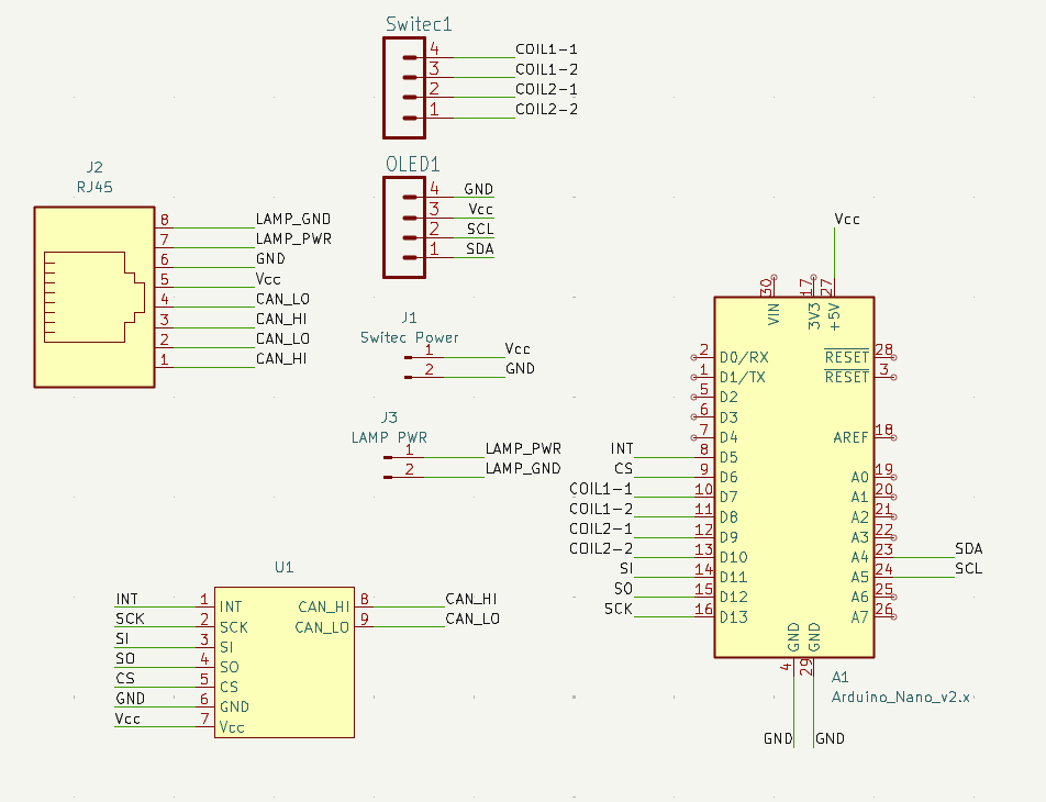
U1 is an MCP2515 CANBus transceiver module. After digging pretty hard through teh webz, I came up empty in trying to find a KiCAD footprint for it. I ended up crafting one myself. Wasn’t hard, but was fiddly. Because the module is aimed at breadboard users, it comes with all the pin headers installed. It looks like this:
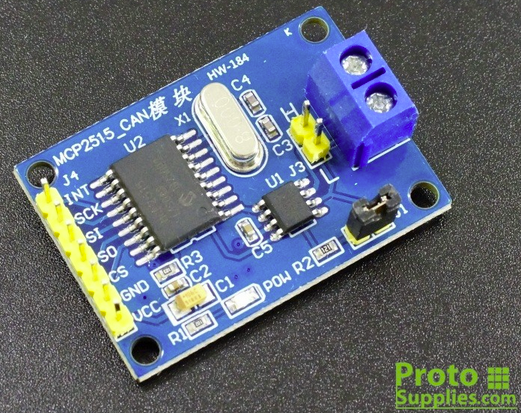
I had to create the footprint in KiCAD such that when installed face down on the PCB, all the headers would line up and the signals would be correct. If I had the opportunity, I’d get these without the headers installed, so I could install turned-pin headers in from the bottom. That would allow me to drop it on the PCB with the components facing up. The jumper on the board is for the 120 ohm terminating resistor that the last item in a CANBus network requires. (one at each end)
The board layout is the same width as my original PCB design (27.61mm), but grew from 50mm to 115mm in length. The extra length is needed to support the CANBus module and the RJ45 interconnect. Below is what the board looks like in the PCB editor:
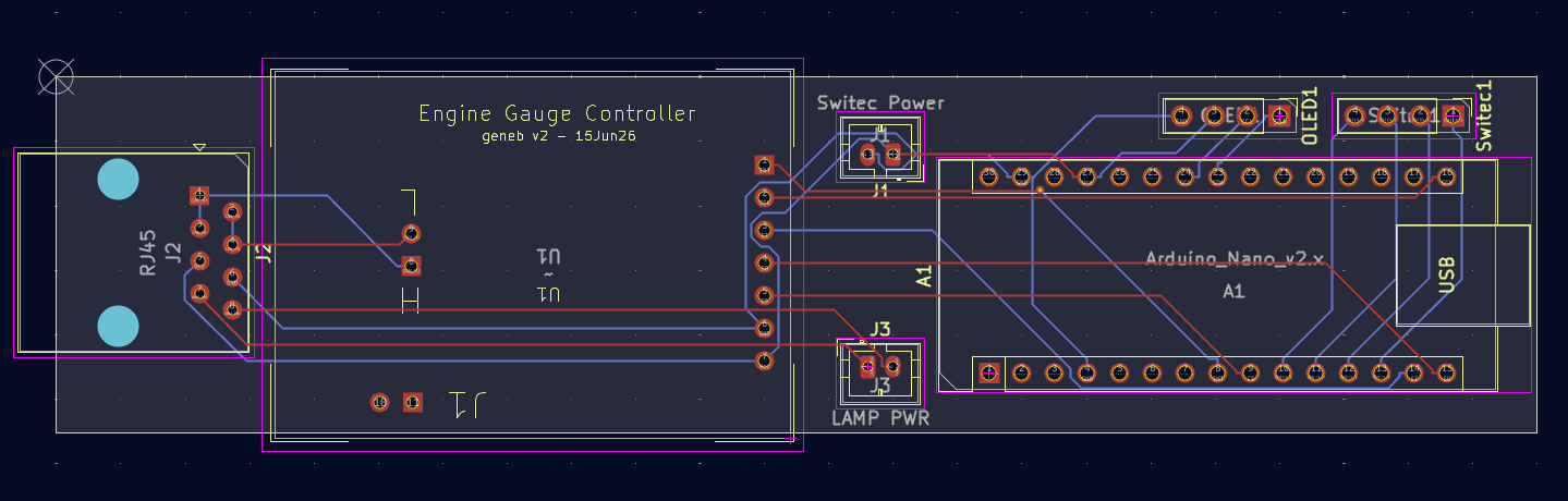
I still need to sit down and build one on a breadboard to validate the design before I order PCBs. I figure if I carefully follow the schematic for the breadboard build, I should be pretty safe to order boards (if it works).
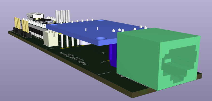
KiCAD has a very cool feature where you can spit out a 3D model of the design, including the components – providing you’ve got all the 3D models for them. I had to chase down the Arduino Nano and MCP2515 module models from GrabCAD. (Great resource that!) Here’s the end result:
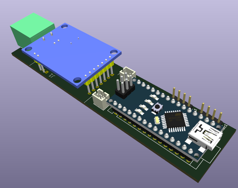
KiCAD can spit out a STEP file that I can bring into Fusion or SolidWorks in order to ensure I’ve got the interior space in the gauge body for this monster. It’ll also help accurate locate the hole for the RJ45 connector in the back of the gauge. I plan on 3D printing the PCB by itself in order to validate the footprint I created for the MCP2515 module.
Comments
Leave a Reply


Ivan Marchiotti on 06.25.2026
Hi there,
please, did you wrote the Arduino program for driving a air core instrument?
Simple example …
I saw it on Youtube. (f15sim)
Kind regards!
admin on 06.25.2026
I did, but it wasn’t usable and I didn’t take the time to figure out why. The air-core motor made a LOT of noise while it moved.