

CAS panel rebuild & wiring harness is complete.
Last Saturday I took some time do de-pin the cannon plug in preparation for rebuilding the CAS panel. This weekend I finally got around to getting that panel rebuilt and wired into the left side console harness.
Here’s a few pics of the rebuilt panel assembly:
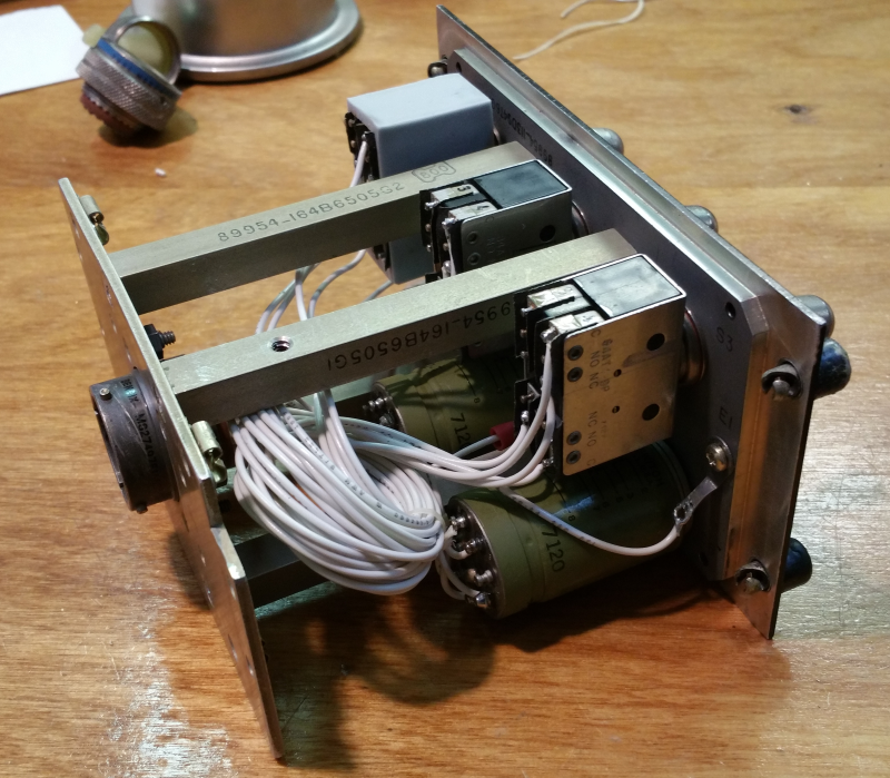
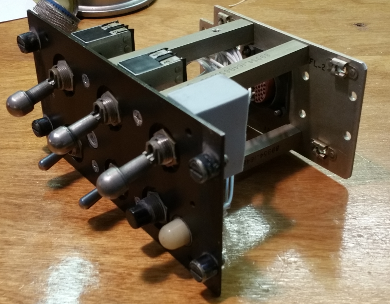
The CAS panel is interesting in that it’s got a pair of magnetically held toggle switches. It’s essentially a relay that’s designed with a very heavy spring to keep it open unless the coil is holding it closed. Here’s what one looks like:
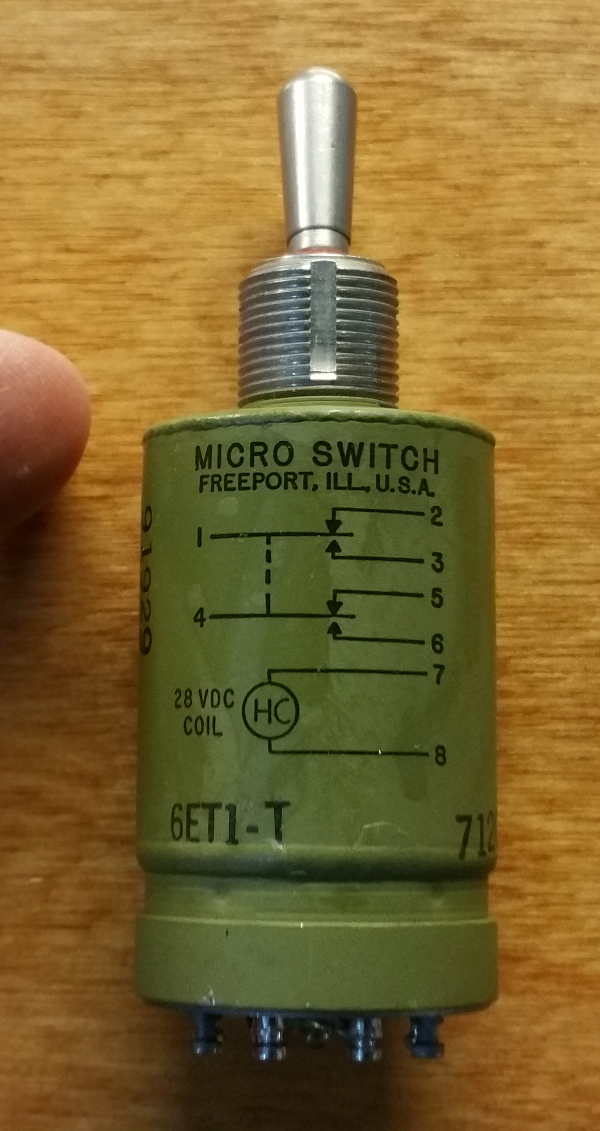 Fingertip for scale. 🙂
At some point I’ll post the little video I did that shows how the switch operates.
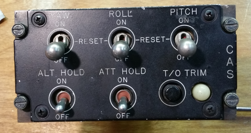
It turns out that I may have a pretty special CAS panel. I noticed the manufacture date & serial number on the back of the edge-lit panel:
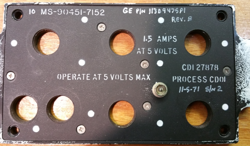
The date is November 5th, 1971 with a serial # of 2. This makes me think that the panel may be from one of the original test articles that MD built, but I’m not sure. I’ll update this post if I find out more information.
New gauge design!
I spent quite a while working on getting the air core motors to work properly. The biggest issue was the sound they made due to the PWM signal resonating in the instrument shell. I did get the sound to go away, but at the required frequency the motor would no longer move properly. This lead me to look into other methods I could use that would still fit into a 2″ MS33639 instrument shell.
Many years ago I briefly looked into the micro stepper motors made by Switec. They were fairly new on the scene and were nice, but expensive motors. Fast forward about 12 years and I find that you can obtain these motors for as little as $2.50 each! (lot of 25 on eBay) My search for more information on the motor led me to an Arduino project where the goal was to use these steppers in various projects. The cool thing is that due to the low power consumption of the coils, they could be directly driven from an Arduino without the need for an h-bridge chip! (20mA per coil) The blog entry that I found is here: http://guy.carpenter.id.au/gaugette/2012/01/05/what-is-gaugette/ – I’d recommend you read the rest of his blog – there’s a ton of great information on using Switec motors, including with a Raspberry Pi.
I did a bit more research and found a demonstrator project on Tindie that used a Switec motor – https://www.tindie.com/products/TheRengineer/analog-gauge-stepper-breakout-board. The board allowed for easy connection to an Arduino and included clamping diodes to prevent back-EMF from doing damage to the Arduino. Since the board was way too large for my needs, I re-designed it to use surface mount diodes (LL4148) and reduced the size of the board to match the diameter of a Switec motor.
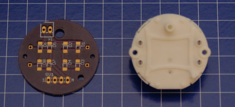
The 4 pin connector along the bottom is for the two coils in the motor and the 2 pin connector at the top is for the 5v reference voltage for the diodes.
I revised my gauge code to use the Switec X25 library and it works great! The motor I’m using is the X27.168 and has an internal stop. The 2″ gauges in the F-15 don’t require more than 300 degrees of rotation at the most, so this is a perfect choice – it allows me to rotate backwards to hit the stop and then start from a known point. The idea being to use the stop in lieu of a “home” position detector.
Unfortunately, changing to the Switec motor required that I completely re-design the “middle” section of the gauge.
Here’s the result of that redesign:
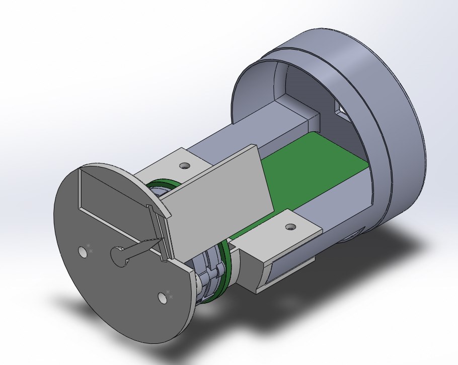
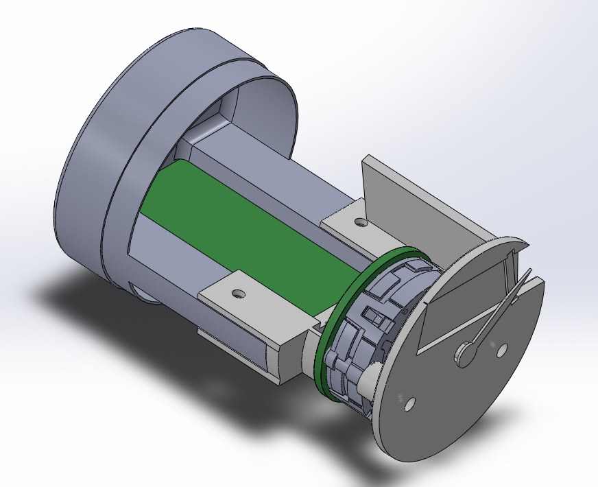
The resulting assembly is going to be roughly 3/4″ shorter than the original, air-core based design. I’m currently printing the new components as I write this. The photo below is the new center mating clip.
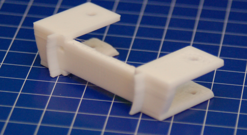
This part attaches to the back half of the instrument using two screws. It is connected to the motor and instrument face using a pair of 0-80 screws that pass through the stepper motor and end up in heat-set inserts installed in the standoffs on the instrument face.
I also got the chance to get the finishing touches done on the gauge face graphics. I had them printed up on 120lb card stock at Staples:
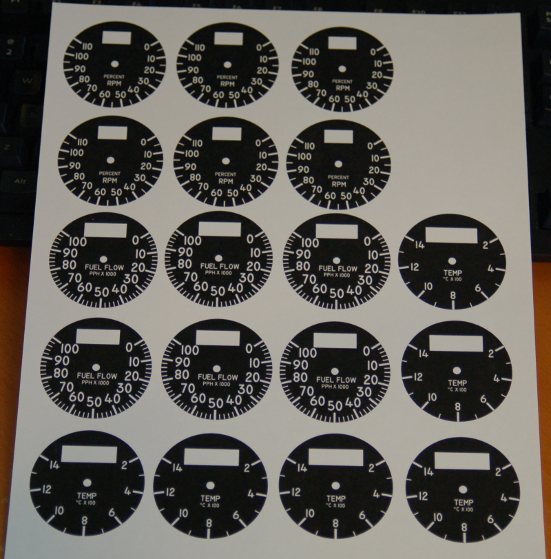 The plan is to cut them out on the laser and then glue them to the gauge faces after assembly. I had enough made to ensure that I’ll have spares when I inevitably screw one up. 🙂 I really like how they turned out!
Thanks for reading!

