

Back in 2015, I began working on replicas of the Fuel Flow, FTIT, and RPM gauges. The gauge design at the time was based around an air-core motor manufactured by SimCo (specifically, https://www.simcoltd.com/products/coil-bobbin-assemblies)
Air-core motors are frequently used in automotive instrument clusters for things like the speedometer, fuel gauge, etc. The units I had were part of a group-buy that I participated in that was run by a number of F-16 cockpit builders. Air-core motors are similar to synchro resolvers in that they’re driven by a sine/cosine signal. Unfortunately for me, I was unable to work out how to drive the motors silently. While they moved fine, there was a high-pitched tone emitted by the motor, which realistically wasn’t something that could be easily ignored. At the time I lacked the attention span to tackle the problem and figure out what the root cause was.
The gauge design sat idle until around June of 2016. About that time I was able to collect enough attention span to chase down a simpler solution to the problem. Instead of working out why the air-core motors whined like I’d stolen their candy, I just swapped over to Switec stepper motors!
It turns out in the years between the group-buy of air-core motors and when I started actually working with them, a Swiss company named Switec had developed a range of stepper motors specifically designed for use in automotive instrument clusters and other pointer-style gauges. The motors turned out to be a perfect solution to my noise problem. They had the range and resolution I needed, the gear hysteresis was no where near as bad as an R/C airplane servo, and they were inexpensive.
Another bonus turned out to be their low operating current. The coils in a Switec motor only consume 20mA each, making them safe to directly drive off the output pins of an Arduino Nano, and no driver chip was required.
The blog entry on that “new” gauge design can be found here: https://www.f15sim.com/?p=407.
During that summer I was able to get the gauge design to what I would consider 90% “mechanically complete”. Unfortunately, the Raging Squirrel of Distraction came along at some point and I started chasing some other stupid shiny thing. (This is an ongoing theme with this project.)
Fast forward a decade, and I’m back at working on the gauge design. The power of ADHD folks. It’s no fuckin’ joke.
The 10 year separation between the original design and now is probably a good thing. I say that because the design skill I’ve got now is light years ahead of what I had then.
The first thing I did was streamline the way the interior gauge elements were assembled.
The prior design looked (mostly) like this:
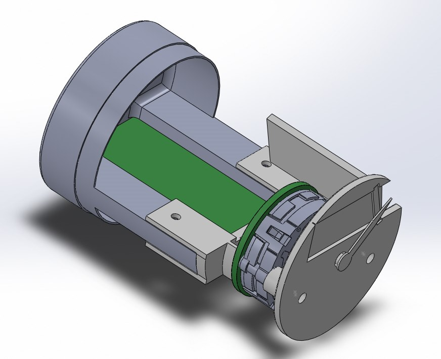
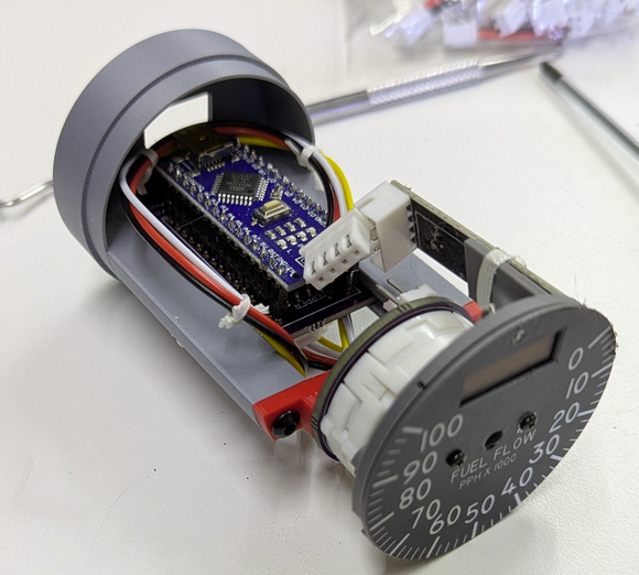
The gauge is split into two parts – the back section carries the interface electronics, and the front half carries the Switec stepper motor and the 0.96″ 128×32 OLED module that displays the rolling numeric display. Because the “window” for the OLED was fixed in place due to the lack of adjustment room for the display itself, this one mechanical design is used to cover all three engine gauge types.
The first thing I did was dump the horrible bracket that joined the sections together. Here’s a photo of what the first pass to the redesign looked like. You can see I’d not yet deleted the vertical mounting holes from the previous design.
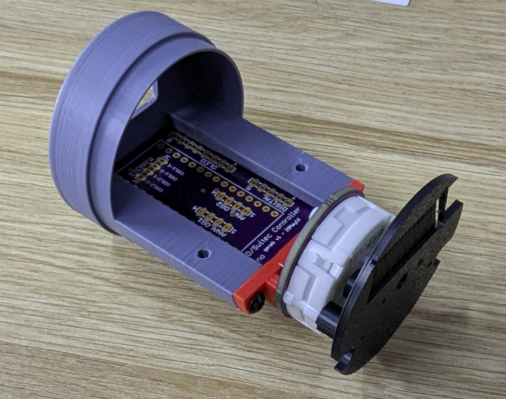
The red component is the entire replacement bracket. The gauge face has two standoffs that are lined up with the Switec motor, and each one has a bore that is sized to allow a #0-80 screw to cut threads into it. I use two 1″ long, #0-80 flat head screws to assemble the motor section. That consists of the red bracket, the motor & pcb, and finally the “face” that the OLED is mounted to.
The two instrument sections are joined with a pair of pan head M3 screws. I’m much more satisfied with this design than I ever was with the previous one, that’s for sure.
This left me with two features to implement. An attachable gauge face, and a method of lighting it.
My 2015 design was going to use laser-cut card stock faces glued directly to the OLED carrier. The 2026 design opted instead to implement a completely separate gauge face that would be screwed to the OLED mount with a pair of short #0-80 screws. This design is in line with how real aircraft gauges are made.
This is the first pass on the gauge face for the Fuel Flow gauge:
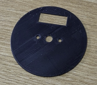
The face is right around 0.025″ thick and was printed using a 0.2mm nozzle on my A1 printer.
For the face artwork, I decided I’d rather go with some kind of printed vinyl decal that could be applied to the face. I figured the result would be a lot better than the laser-printed card-stock I’d had printed a decade ago. It would also give me “blacker” blacks than I had with the laser printed version.
The downside to that decision is that since I don’t have a printer capable of printing on sign vinyl, nor a suitable vinyl cutter, I had to outsource the job… I reached out to a local sign shop and they’d be happy to help! Unfortunately, they had a minimum size requirement that resulted in my now having 12 each of the three gauge face types, and at a cost of nearly $200. Yikes!
The up side to that is the results I got are absolutely perfect, and their machine handled all the cutting for me, including the OLED and pointer windows.
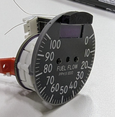
Below is a photo of the new face assembled to the 2026 gauge design:
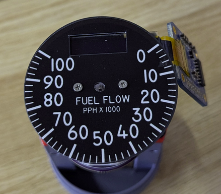
Unfortunately, the gauge designs I had printed are missing two features – the face mounting holes to either side of the pointer opening, and two holes at the top for the 5V lamps used to illuminate the face….which brings us to the next task – lighting the gauge face.
Aircraft gauge lighting typically comes in one of two methods – “trans-illuminated” where the lamps are behind a translucent gauge face and illuminate any markings designed to allow light to pass through them. The other method is “face illumination”, where the lamps are aimed at the outside face of the gauge via light pipes or direct lamp exposure.
Fortunately for me, the engine gauges in the F-15 use the “face illumination” method.
Below is a photo of a real Fuel Flow gauge, tilted to see where the lamps are:
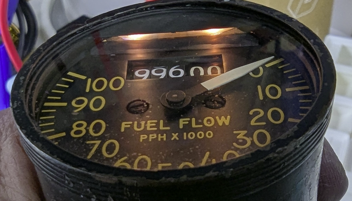
As you can see, the whole face is lit by only two lamps. This is a good thing because it makes for simple implementation. A light pipe that surrounded the gauge face would have presented a number of design challenges.
The two lamps are 5V bulbs that are about 0.125″ in diameter. Fortunately I’ve got a lot of these from the Type 5 side console panels I built. In order to fit the lamps in the correct spot, I added holes to the gauge face and OLED support face designs, and created a “hood” printed from translucent PETG:
You can see the “hood” at the top of the instrument. The bulbs slide forward into that, and only the bottom surface is unpainted. The face profile of the hood matches a masked area on the instrument glass, which hides it perfectly, just like the original.
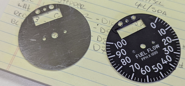
Another improvement I made was to change from a 3D printed face to one that was made from 0.025″ thick aluminum. In this case, Send Cut Send came through with absolutely perfect results. I suspect they used a laser to cut these.
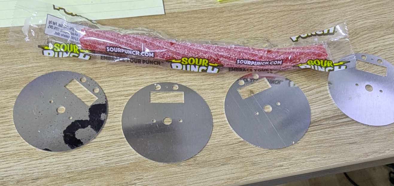
The bonus candy was nice. 🙂
The down side to not having the lamp and mounting holes in the new vinyl faces… It’s not a show stopper though. A sharp hobby knife can fix it quick.
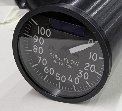
The photo below shows what I consider to be the 99% “mechanically complete” design:
I say “99%” because the instrument length will be increasing once the electronics are updated. The original design used an Arduino Nano as the “brains” and was connected to the host PC via USB – the instrument would enumerate as a serial port on the host computer.
The new electronics will continue to use an Arduino Nano, but communication will be handled over CANBus. This requires a redesign of the PCB in order to include the new MCP2515 CANBus transceiver module. Another change made was to go from the SPI OLED display to one that communicates via I2C. The SPI interface to the OLED was 7 wires and the I2C interface is only 4, and the OLED driver board is just about half the size of the SPI versions.
The new PCB design will start as soon as I’ve gotten it proven out on a breadboard, which should happen in the next week or so. Here’s a short clip of the “odometer” effect I created for these gauges. It works very well!
Comments
Leave a Reply


Ivan Marchiotti on 06.25.2026
Hi there!
Please, I have a question regarding your Arduino air core
program. I find it on Youtube.
How can i reach/contact Mr.Gene Buckle?
Kind regards
Marchiotti Ivan
admin on 06.26.2026
Just ask questions. 🙂 FYI, I put the original test code here: https://github.com/geneb/air-core-test-code. I included a schematic with it.