The new panel that I’m working on is for the IFF control panel in the F-15. Since I have a “real” edge-lit panel for this, I only need to make the metal mounting plate and the “REPLY” indicator that it needs.
Here’s what the panel itself looks like:
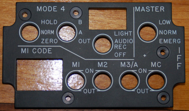
IFF Control Panel
The image below shows what a “real” panel looks like:
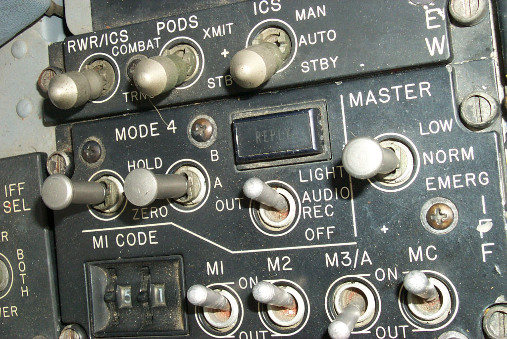
IFF panel from the McChord AFB Museum F-15A
The 2 digit rotary numeric selector (the “M1 CODE” wheels) is a part I already have in stock. The only tricky part is the REPLY indicator. To find the “real” part would take considerable effort and would likely cost a lot more that it’s realistically worth. This means that I get to scratch build one.
I start off by creating the lettering portion of the indicator and then test-engrave it on my laser using a 3×5 card as test stock:
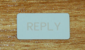
Test indicator face
The font doesn’t exactly match the indicator on the real panel, but since this is more experiment than anything else, it’s ok. This will be the first from-scratch indicator I’ve built since I got the laser.
The next step is to cut the parts needed to hold the LEDs that I’ll be using to illuminate the indicator from behind:
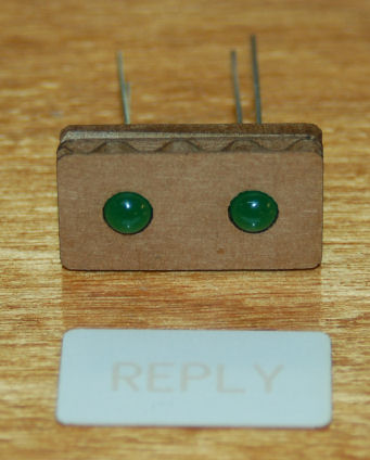
The LED holder was cut from regular cardboard. It’s pretty close to the thickness of the acrylic I’ll be using and is tons cheaper to screw up. 🙂
The first version of the LED holder didn’t have the mouting hole in the center, but it was worth the waste to make sure that it was going to assembly correctly:
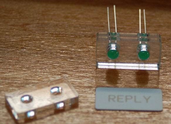
Now in order to make the face of the indicator, I needed to cut the indicator face out of 1/16″ acrylic and then prepare it like so:
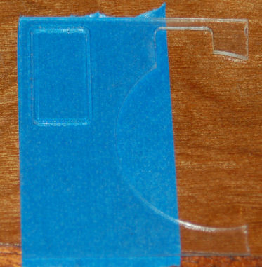
Masked indicator face ready for painting
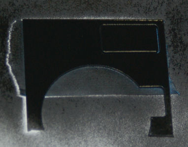
Freshly painted indicator face.
When finally engraved on the laser, it came out like this:
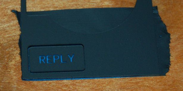
I then cut new back parts to include the threaded hole for a #6 mounting screw. The base layer was also cut from black acrylic instead of clear.
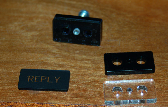
All the indicator parts together.
After getting this far, I went ahead and assembled the circuit board that would hold the two 5MM LEDs as well as the 470 Ohm resistor that would allow me to power them with 12VDC. Unfortunately I had forgotten that your typical LED only has a field of view of about 60 degrees. This resulted in nicely lighting up the “R” and the “Y” while leaving a lot of dark space in between. Thanks to Mike Powell, I now have some 180 degree LEDs on order. When they arrive, I’ll post pictures of the assembled indicator.
The new indicator won’t use the indicator face as shown above. I’ve since found a local supplier of a special Rowmark plastic that has a very thin black acrylic layer and a thicker clear layer. This will allow me to create a better looking indicator. I’ll use the correct font for the new example as well.
Comments



Wilson on 05.27.2009
Wow,
Very impresive.
admin on 05.27.2009
Thanks Wilson. More will be posted soon. I’m still waiting for those 180 degree FOV LEDs to show up. 🙂
IFF & EW panel work : F-15C Flight Simulator Project on 06.08.2009
[…] correct, but the bat handles are not. You can see what the correct toggle switches look like in this post. I’m going to hold off on final assembly for a little while to see if I can find the […]