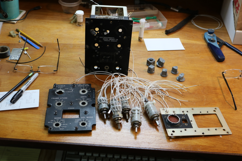
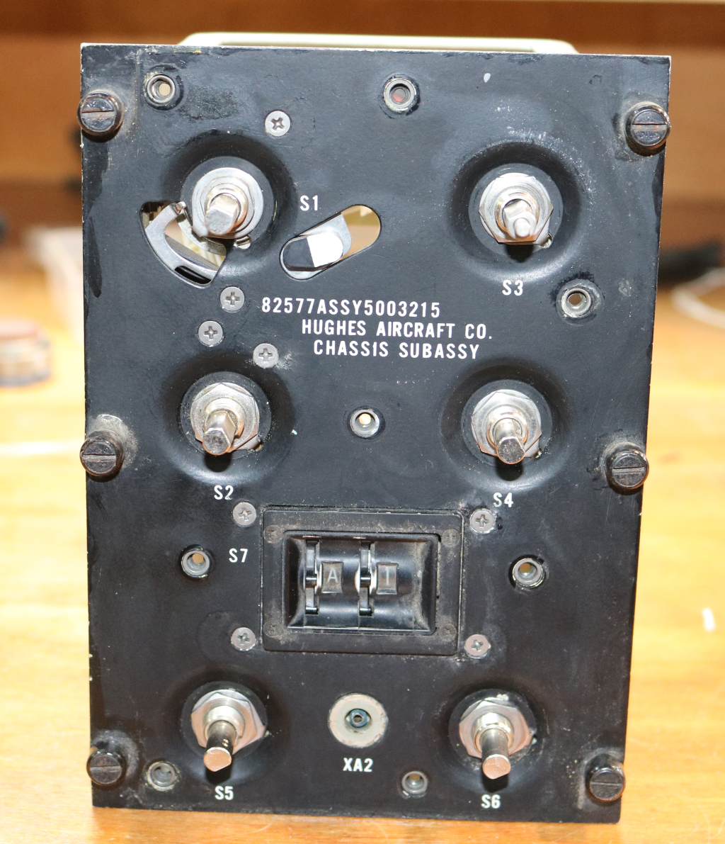
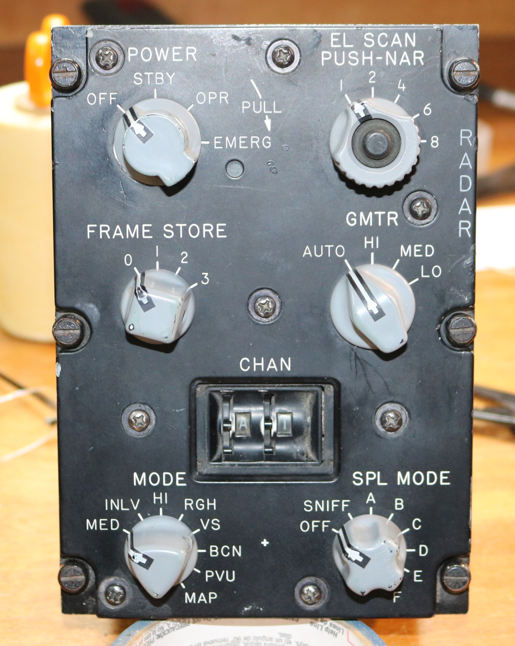
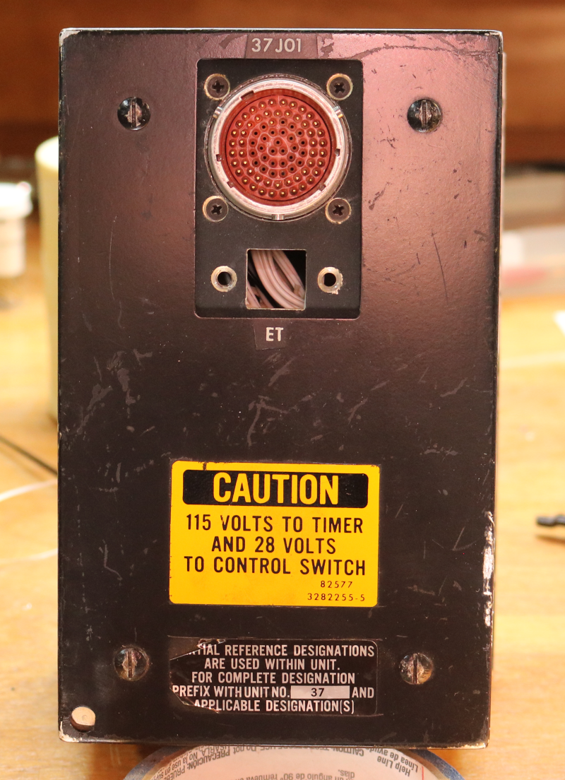
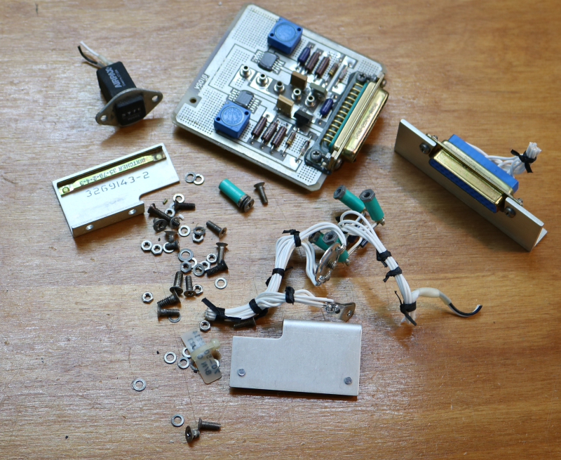
Last Saturday I took some time do de-pin the cannon plug in preparation for rebuilding the CAS panel.  This weekend I finally got around to getting that panel rebuilt and wired into the left side console harness.

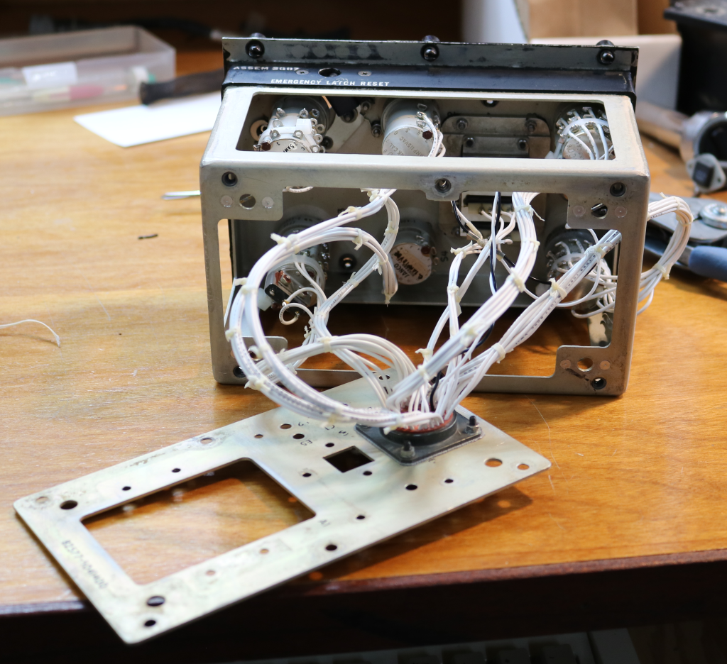
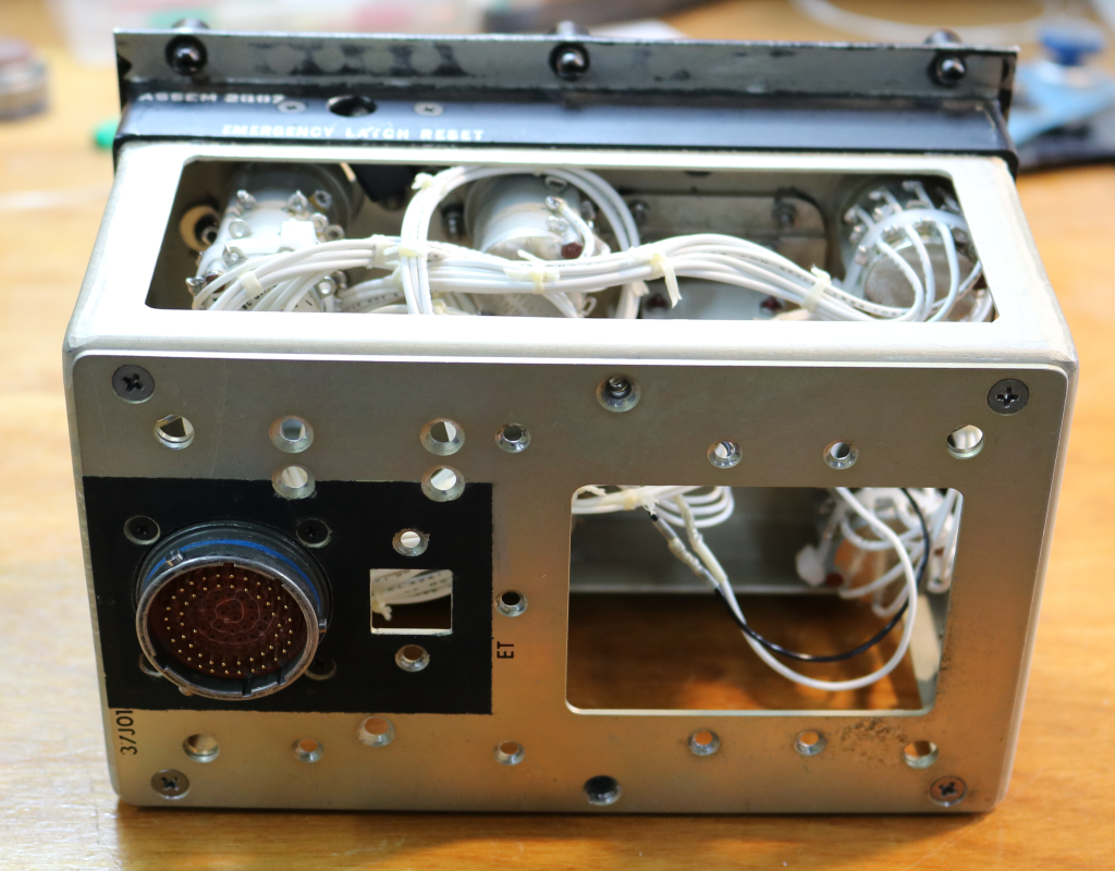
Here’s a few pics of the rebuilt panel assembly:

rebuilt-cas-1rebuilt-cas-2

rebuilt-cas-3

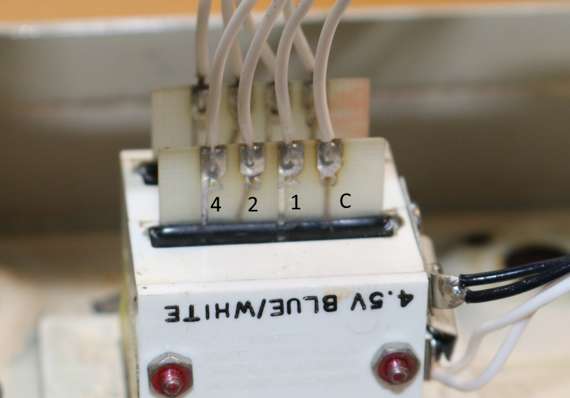
The CAS panel is interesting in that it’s got a pair of magnetically held toggle switches.  It’s essentially a relay that’s designed with a very heavy spring to keep it open unless the coil is holding it closed.  Here’s what one looks like:

mag-switch-1Fingertip for scale. 🙂

At some point I’ll post the little video I did that shows how the switch operates.

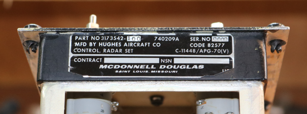
It turns out that I may have a pretty special CAS panel.  I noticed the manufacture date & serial number on the back of the edge-lit panel:

cas-panel-back

The date is November 5th, 1971 with a serial # of 2.  This makes me think that the panel may be from one of the original test articles that MD built, but I’m not sure.  I’ll update this post if I find out more information.


06.04.2016

I spent quite a while working on getting the air core motors to work properly.  The biggest issue was the sound they made due to the PWM signal resonating in the instrument shell.  I did get the sound to go away, but at the required frequency the motor would no longer move properly.  This lead me to look into other methods I could use that would still fit into a 2″ MS33639 instrument shell.

Many years ago I briefly looked into the micro stepper motors made by Switec.  They were fairly new on the scene and were nice, but expensive motors.  Fast forward about 12 years and I find that you can obtain these motors for as little as $2.50 each! (lot of 25 on eBay)  My search for more information on the motor led me to an Arduino project where the goal was to use these steppers in various projects.  The cool thing is that due to the low power consumption of the coils, they could be directly driven from an Arduino without the need for an h-bridge chip! (20mA per coil) The blog entry that I found is here: http://guy.carpenter.id.au/gaugette/2012/01/05/what-is-gaugette/ – I’d recommend you read the rest of his blog – there’s a ton of great information on using Switec motors, including with a Raspberry Pi.

I did a bit more research and found a demonstrator project on Tindie that used a Switec motor – https://www.tindie.com/products/TheRengineer/analog-gauge-stepper-breakout-board.  The board allowed for easy connection to an Arduino and included clamping diodes to prevent back-EMF from doing damage to the Arduino.  Since the board was way too large for my needs, I re-designed it to use surface mount diodes (LL4148) and reduced the size of the board to match the diameter of a Switec motor.

switec-and-pcb

The 4 pin connector along the bottom is for the two coils in the motor and the 2 pin connector at the top is for the 5v reference voltage for the diodes.

I revised my gauge code to use the Switec X25 library and it works great!  The motor I’m using is the X27.168 and has an internal stop.  The 2″ gauges in the F-15 don’t require more than 300 degrees of rotation at the most, so this is a perfect choice – it allows me to rotate backwards to hit the stop and then start from a known point.  The idea being to use the stop in lieu of a “home” position detector.

Unfortunately, changing to the Switec motor required that I completely re-design the “middle” section of the gauge.

Here’s the result of that redesign:

v2-gauge-iso-1-sm v2-gauge-iso-2-sm

The resulting assembly is going to be roughly 3/4″ shorter than the original, air-core based design.  I’m currently printing the new components as I write this.  The photo below is the new center mating clip.

center mating clip

This part attaches to the back half of the instrument using two screws.  It is connected to the motor and instrument face using a pair of 0-80 screws that pass through the stepper motor and end up in heat-set inserts installed in the standoffs on the instrument face.


I also got the chance to get the finishing touches done on the gauge face graphics.  I had them printed up on 120lb card stock at Staples:

gauge facesThe plan is to cut them out on the laser and then glue them to the gauge faces after assembly.  I had enough made to ensure that I’ll have spares when I inevitably screw one up. 🙂 I really like how they turned out!

Thanks for reading!

I finally had the time to come back to the gauge and get the firmware finished!

I had somehow managed to do damage to the Arduino Nano such that you couldn’t upload firmware to it using the “normal” method in the Arduino IDE.  Turns out I’d blow the rxdata line going into the ATMega 328 MCU on the board. 🙁  The good news is that I’ve got it replaced and the firmware is done.  Next step is to make some high quality faces, new needles and new instrument shells.

Here’s an interesting bit of trivia for you – the F-15C can consume up to 150,000lbs of fuel per hour at low altitude and in full afterburner.  That’s right around 22,000 gallons of fuel per hour!  Those F100-PW-220 engines are hungry! 🙂

So the printed circuit boards mentioned in the previous entry have been put to work!

The gauge shown here is the core that I’ll build the six 2″ engine gauges out of.

Here’s what the gauge looks like on the inside.  All the plastic components (the white bits) are 3D printed on my SeeMeCNC Rostock MAX v1, Orange Menace.

gauge interior, side

gauge interior, side 2

Here’s how it looks with the “test” case on it:

gauge front

Finally, here’s a short video of the gauge in operation:

Once I have the time, a properly sized case will be printed (the blue one is too short) and I’ll get a good laser engraved face on the gauge.

It’s coming along! 🙂

[Here are the gauge electronic components, sans header connectors]

gauge-electronics

I’ve recently been working on getting the six engine gauges for the F-15 put together.  Since I’m not going to be using real instruments, I needed to scratch build them.  Last year I did a short demo that shows how I’m using a small OLED display to emulate the “odometer” style display that’s used in the Fuel Flow, Temperature and RPM gauges.  I finally got around to doing the software integration and did a short video that shows both the air core and the OLED display working together:

Some weeks later, the boards I ordered from Osh Park arrived and I got the first one soldered up.

board-topboard-bottom

This is the top of the new interface board.  The chip in the center is an LM293DD dual h-bridge chip.  This is the surface mount version of the LM293D that I bread-boarded the circuit on.  The header on the right goes to the OLED interface.

The bottom of the board has a four pin connector that will go to the air core motor.

board-assy

This is what the final assembly looks like after the Arduino Nano has been mounted.

The USB connector is at the back end of the board and will be accessed through an opening in the back of the instrument.  I’m still working on the design for the instrument core, so I don’t have much else to show yet.

More soon!


07.25.2015

I don’t know if this update qualifies as a “milestone” or not, but I finally finished and installed the wiring harness for the right side console!

The adventure started this morning with the construction of the wiring harness for the recently finished TEWS panel.  This consisted of cutting, stripping and adding pins & sockets to the 22 wires that are used by the TEWS panel.

Weapons of choice...

Weapons of choice…

Read more

Wow.  It’s been a while since I’ve posted an update!  Since the last update, I’ve nearly finished the re-wire job for the right side console.  I was fortunate enough to get a pile of brand new canon plugs and matching pins.  This is allowing me to re-wire the cockpit using the original bulkhead connections, which makes for  a much neater build!  In order to build the wiring harness, I’ve had to build it out panel by panel.  With the completion of the TEWS panel, the wiring harness will be completed.  The only thing missing will be the CMD panel that controls how the chaff & flare dispensers behave.  I’ve never been able to get a photo of that panel, so I’m going to hold off until I do and can make a new one from scratch.

The navigation control panel is going to be a stand-alone, USB interfaced device due to its complexity.  That should be an interesting rebuild.

I started the TEWS panel rebuild nearly 3 years ago, which is kind of embarrassing.  In my defense, I DO have a lot going on.  There’s good reasons it’s been 15 years since this project started. 🙂

When I first wrote about the TEWS panel, I pointed out that I needed to replace the two destroyed Korry “FAIL” indicators that the panel had.  I decided to go a different route than the Korry replacement I built for the IFF panel.

Read more

First up, here’s what the new SFS interconnect cable looks like:

new-sfs-interconnect-cable

The end of the cable on the right is bolted to the cockpit floor and the other end winds its way along the pitch axis bearing and up the centerline of the roll axis section.  It attaches to the bottom of the SFS box in order to bring the signals from the SFS box & grip to the control interface hardware that’s going to be installed in the left side equipment bay that’s under the cockpit.  The clear plastic tube was part of the original SFS interconnect cable.  I was able to salvage it for the new cable.

sfs-interconnect-end

Above is a shot of the SFS end of the cable right before I closed up the outer sleeve.

I’ve been working on getting the inboard throttle grip rebuilt.  Having friends in interesting places helped out quite a bit with this part of the project.  The F-15C inboard grip contains a “slew” control, which is essentially a tiny little force sensitive joystick.  It’s used as the Target Designation Cursor controller.  You can see it in the photo below, the “L” shaped object.

The slew control requires an input amplifier because the signal it puts out is very, very tiny.  This is where my smart buddies come in.  They make an interface board that is specifically designed to turn these slew controllers into joystick axes.  The board supports the slew control as the main x/y axis and has a few other goodies on it that make for a complete joystick interface.  Below is a pic of that board.

[31Aug15 Update!]

A few people have emailed me asking about more information on the slew control -specifically the pinout.  Here you go!

Pin 1 – 5VDC
Pin 2 – X Axis
Pin 3 – Y Axis
Pin 4 – GND

I should also note that one the folks that emailed me was able to successfully get the slew control working by using the analog inputs on an Arduino!

Read more

04.06.2014

After a very, very long delay, the SFS box is finally finished.  There’s literally nothing left that needs to be done for it. 🙂

From last weekend’s work, here’s the last two stages of wiring.

First, lace it up!

sfs-wired-1

Then it gets cleaned up and attached to the interior of the SFS box.

sfs-wired-2

I use a LOT of waxed lacing cord.  It makes for a very nice looking wiring harness and doesn’t snag on everything like a nylon wire tie will.

The next three photos show the completed SFS box with the grip attached.

sfs-grip-1 sfs-grip-2 sfs-grip-3

And finally, here’s what it looks like installed in the cockpit!

sfs-installed

I really, really need to dust. 🙂


This past weekend saw some renewed effort on the project.  For the last 18 months I’ve been up to my neck in 3D printer things – I’ve been writing the assembly and user guides for SeeMeCNC’s line of excellent 3D printers. http://www.seemecnc.com

One of the things I got done was to finish the missing pawls for the throttle quadrant and get them installed.  These pawls act as both an idle gate bar and as a trigger for the engine start switch.  In order to pull back past the idle gate, you need to pull up on the finger lift.  This prevents you from accidentally cutting fuel off to the selected engine when pulling the throttle fully aft.  When starting the engines, you pull up a finger lift and the pawl activates a microswitch that in turn causes the JFS to link the AMAD to the selected engine.

Here’s the new pawls – the originals were sold unfortunately.

New throttle pawl parts & drawing

New throttle pawl parts & drawing

Here’s a photo of what the new parts look like installed:

Pawl installed

Pawl installed

#1 is the idle gate.  When the pawl is forward of it, you can’t pull the throttle arm fully aft without lifting the pawl over it.

#2 is the engine start switch.  When the pawl is aft of the idle gate, pulling up the finger lift will cause the pawl to engage the switch.  The sides of the pawls are 3D printed from ABS plastic.  I may replace those printed parts with machined aluminum before installation back in the cockpit.

The other thing I got accomplished was the fitting out of the SFS box!  That’s been a long drawn out project for sure!  I got the Nosewheel Steering/AP Disconnect paddle & switch installed on Saturday and I completed the wiring & other assembly this evening.

Here’s the start of the process:

SFS wiring parts.

SFS wiring parts.

The Post-MSIP II grip I have uses 23 wires to cover the six switches on the grip.  An additional two wires are needed for the NWS/AP Disc. paddle.  The silver connector shown above is the female connector that the grip mates to and was a surplus item a friend scored for me.  The very “used” looking connector behind it was the floor-mounted end of the SFS wiring harness that went from the cockpit floor up to the bottom of the SFS box.  Since the connectors are insanely expensive (roughly $175 for this one), I decided to re-use existing connectors whenever I could.  The other end of the SFS wiring harness will mate to this connector and while the floor connector will be different, it will be nearly impossible to tell it’s not original.  This wiring job was a one-way task.  I had inadvertently used 22ga wire instead of 24ga and didn’t realize it would be a problem until I’d put all the female crimp-on connectors in place.  The pin removal tool I have is too small to fit the 22ga insulation properly, thus making the pin insertion a permanent deal.  The pin & socket insertion process took about 20-30 minutes – I did NOT want to make a mistake that would either ruin a connector or cause me to have to cut and splice out a mistake.  Fortunately, I got it right. I think. 🙂

Here’s what the result looks like:

SFS nearly done!

SFS nearly done!

All that remains is for the bottom connector to be screwed into place and then the wiring needs to be wrapped up in lacing tape and tied to the interior of the SFS box.

The final step will be to install the machined Delrin installation post I made a few years ago and get it properly drilled so I can bolt the SFS box to the lower stick assembly.  That should be done this coming Saturday and I’m really, really looking forward to it!


« Previous PageNext Page »