Update for February 12th, 2023.
This weekend saw a bunch of “non-F-15” work done in the shop. I spent Saturday working on the PrintNC project – I bought some “pcnpro” parts that consist of machined aluminum parts for the X & Y roller assemblies. I also previously purchased some replacements for the X & Y roller steel that weren’t cut as square as they needed to be.
In my rush to get the new parts marked & drilled, I got my X & Y axes mixed up and drilled the wrong holes in the X axis roller beam. (That’s a 90mm long bit of 3×2″ steel box beam.), so I had to cut a new one. In order to do that, I had to unbox and set up the new horizontal band saw that I bought. That was originally purchased in order to make parts that I needed for the new canopy hinge support. It took me a while to get the thing dialed in – I’ve never used a metal cutting bandsaw before. It started out making pretty bad cuts – thicker on the bottom than on the top. I sped up the blade and adjusted the force applied so that it cut slower. I got a good enough result after a few iterations that I was able to cut a new bit of steel for the X axis roller beam part. All three parts (2 Y axis roller beams and the 1 X axis roller beam) have been drilled, tapped, and painted. I’m waiting for some new fasteners to show up so I can install them. The “supplied” fasteners are socket head cap screws, and button head screws should really be used to mount them to the HGR carriages. There will be a rant about this when I do the “post mortem” video of the mechanical assembly.
I ordered a 14″ diameter Lazy Susan bearing today in order to build a multi-use platform. The first use will be to support the ACES II Ejection seat while I work on it. I’ve got it up on my main work table so having it on a Lazy Susan will make it easier to work on, and it won’t scratch the shit out of the table when I move it. 🙂
As to the ejection seat, it’s been positively identified as some kind of training device. I got some great feedback from an employee of the company that manufactures them. The number of real components leads the individual to believe that it was originally designed as some kind of procedures trainer for pilots. Investigation of its origins are still ongoing.
I’m going to try to update this site with weekly updates. We’ll see how well that works. 🙂
Finally got a real ejection seat!
Getting a real ACES II ejection seat for the F-15C has been a dream since I got the cockpit section. It took 23 years to do, but I finally got my hands on one!
Check out the “unboxing” video below:
Fortunately it’s not missing critical bits and should prove fairly easy to restore.
Project Re-Launch!
I just dropped a new video that covers the re-launch of the project. It’s time to get shit done.
Canopy!
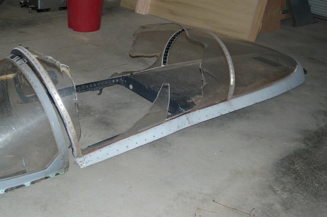
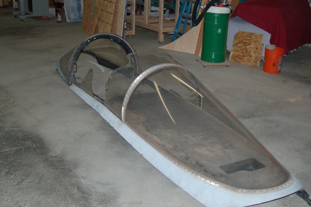
St. Roger, the patron saint of wayward aircraft bits delivered unto me a windscreen and canopy last night!
As you can see, it’s pretty rough. We figure it was either ejected or purposely damaged for whatever reason. It CAN be salvaged however.
Finding a replacement glass section (lexan actually) is essentially impossible. That is ok however, because since I don’t have the part of the fuselage where the hinge mounted, I really can’t make it an articulating canopy anyway.
What I’ll do is remove the broken lexan parts and then mount the canopy in the closed & locked position to the F-15. Without the forward canopy glass there, you can just step over the rail to get into the cockpit.
The canopy is also bent a bit in the middle, but I’m sure I can straighten it out well enough to get it installed. I’ll have to fabricate a replacement trim strip as the one on the left is broken where the canopy is bent.
The good news is that the mounts for the compass and lock/shoot lights are still in place. The side handles are present as well. I can’t wait to get this thing fixed and installed! It’s gonna look kind of odd without the forward glass, but who cares!
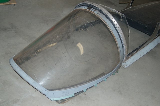
Here’s a shot of the new windscreen:
The windscreen has a few gouges in it, but it’s actually in a lot better shape than the A model windscreen that came with the cockpit when I originally got it. I’m going to test some Novus polish I have to see how well it works fixing some of the lighter scratches. I think Novus also makes a fill that will handle the deeper gouges.
[Update: 20Nov12]
Thanks to Matt who sent me a link to a Craigslist ad for an F-15 canopy, it looks like I may get it. I’m working on making arrangements with the seller right now. How’s that for cool? 🙂
I also got the images resized thanks to a new plugin I found for WordPress called ImagePro.
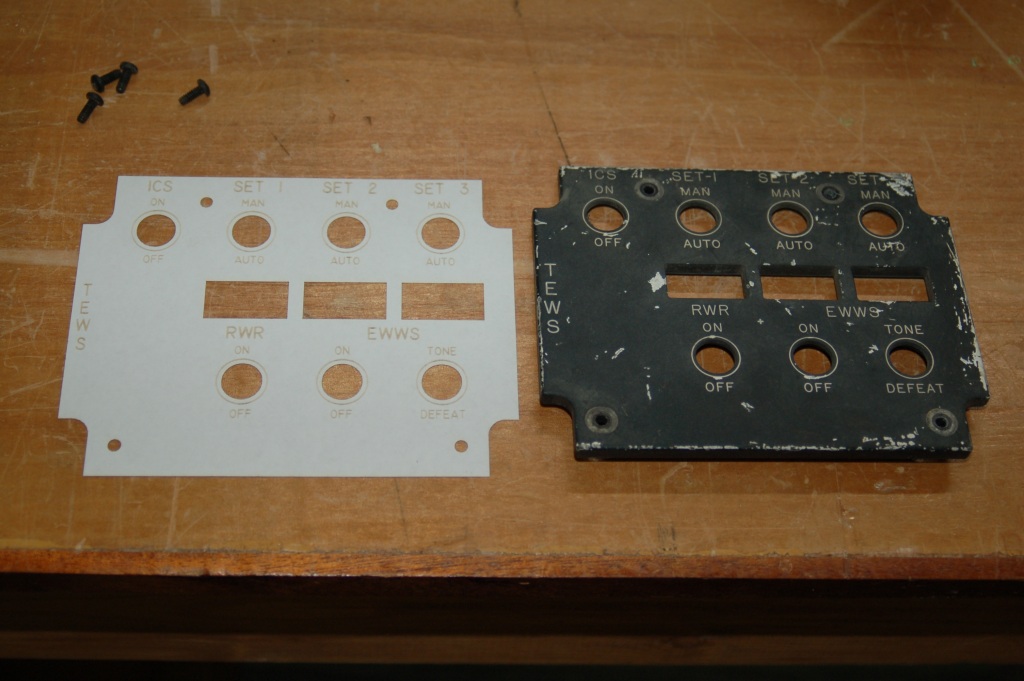
Started the TEWS panel rework…
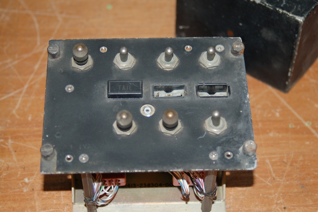
A couple of years ago I scored a nearly complete TEWS control panel from a gent in Cypress. The panel was scuffed pretty badly and some nimrod tore out two of the three FAIL indicators. However, there’s enough left for me to work with. 🙂
As you can see above, the panel itself isn’t in such bad shape except the FAIL indicators.
Last Saturday I started the artwork on the replacement edge lit panel for the TEWS control:
I go through an iterative process that involves measuring the original and transferring those dimensions to an AutoCAD drawing. Periodically I’ll throw an 8.5×11 sheet of printer paper into the laser and cut a test to see how it matches to the original. At the stage this picture was taken, the panel art is complete. The next step will be to duplicate the pocketing on the back of the panel in order to reuse the original circuit board that carries all the grain-of-rice lamps that light up the panel.
After the edge-lit panel is complete, I still need to find two replacement FAIL indicators, otherwise I’ll need to fab three new ones in a similar fashion to what I did for the REPLY indicator on the IFF panel.
Constructing the SFS box, Part 3
This update is going to bounce around a bit – I’m presenting the pictures in the order in which they were taken…
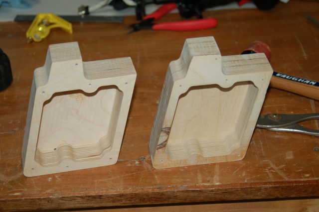
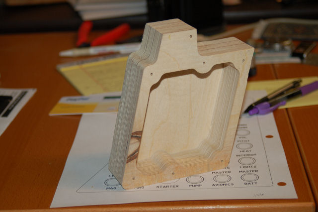
Here are the two SFS box shells right off the ShopBot:
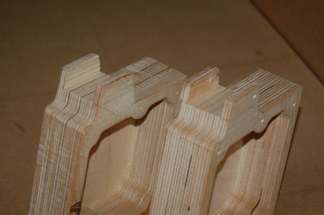
Each one as mentioned before is made from four layers of 1/2″ Baltic Birch plywood.
Space cut out for the Nose Wheel Steering and Auto Pilot disconnect paddle:
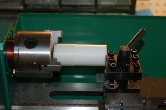
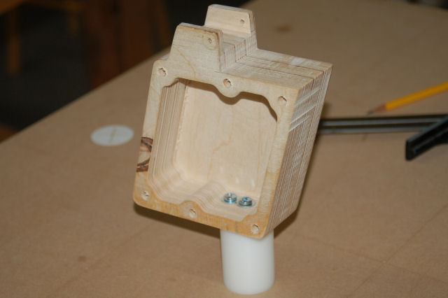
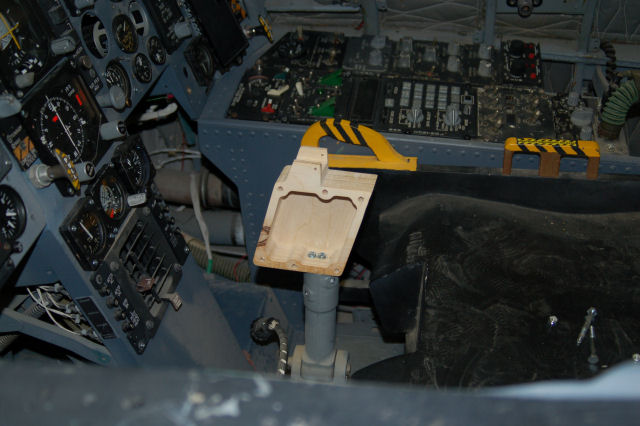
The “real” SFS box is a one piece casting that includes a 2″ mounting post that fits into the stick base in the cockpit. For this version, I had to turn my own post:
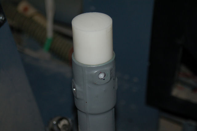
The post blank is a 4″ long section of 1.5″ diameter Delrin. Delrin is a very easy to machine material and is quite strong.
After turning it down to 1.4375″, it’s time to see if it fits…
Insert Happy Dance Here. 🙂
I then cut it down to the 2″ length needed and then drilled & tapped it for 3 #10-24 screws.
…and just one more test fit…
One word. Muahahahahahahaha!
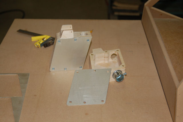
The box sides came next. The sides are .062″ aluminum and I’m using #8-32 brass inserts to allow me to use machine screws with the plywood.
The box to the right is the one that will be in the ‘109F/X.
On a completely unrelated note…
For the poor girl in danger of loosing her Chick License:
Enjoy! *laughs*
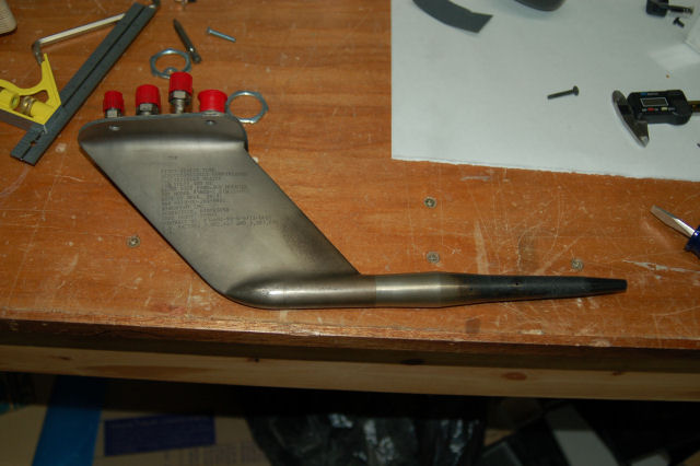
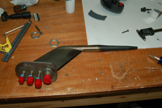
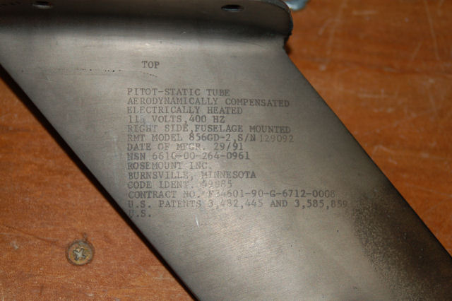
BTW, I do need to find a left-hand pitot tube. This one is for the right side only. 🙂
Thanks for reading!
Constructing the SFS box, Part 2.5
I went to my local acrylic monger yesterday and was captivated by this huge block of gray UHMW. It was _begging_ to become an SFS box.
The block was about 10 inches long, 8 inches wide and 2.5 inches thick. I needed to pare it down to 1.75″ thick first…
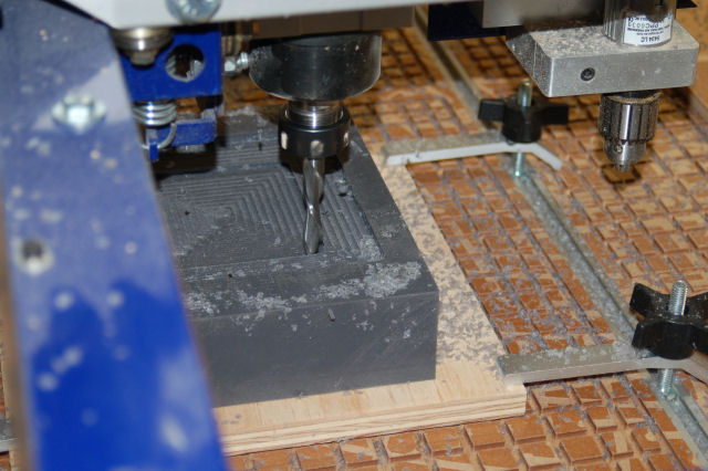
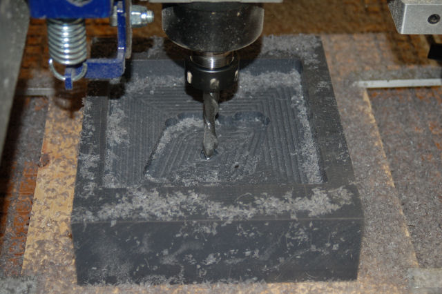
You can see the UHMW chips flying away from the cutter. I’m using a .50″ downshear cutter running at 12,000 RPM with a feed rate of 1.7in/sec. That cutter is an _animal_ in this stuff. I’ve never cut UHMW before and it was definately an experience I won’t soon forget. I’ll be cleaning up little bits of gray plastic swarf for the rest of my life I think.
Now we get on to the interior of the SFS box…
All during the cutting process, I was trying to suck up as much of the swarf as I could with a narrow shop-vac hose. The best I could do is keep the stuff from clogging the cutter…
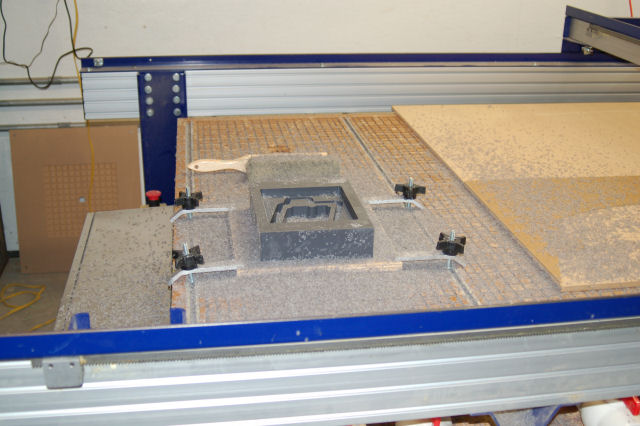
All done! What a f*cking mess. *sigh* The block of material has been glued down to a sheet of scrap plywood with 3M 77 spray adhesive. Worked great!
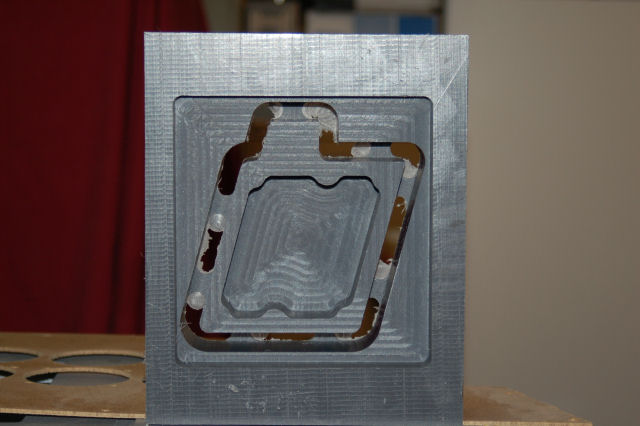
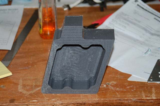
Here’s the end results:
I really don’t care for the finish the cutter left on the box so this will likely be just a fun paper weight. Tomorrow I’ll get the .062″ aluminum cover plates made…
Constructing the SFS Box, Part 2
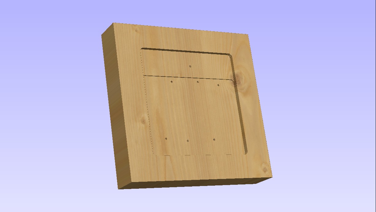
Today I cut the first SFS box core on the ShopBot:
I went ahead and deleted the additional pocket operation that would have inset the aluminum box cover. Now it will more accurately reflect the original part.
A little bit of finish work will be required to correct the bottom edge profiles where the AP/NWS disconnect lever is mounted.
Part 3, coming soon!
Constructing the SFS Box, Part 1
The F-15 uses a very interesting system for the roll and pitch control – it’s both Fly by Wire and mechanical interconnect.
If you were to pin the stick in place with your knees, you can fly the jet by pressure on the grip all by itself, just like an F-16.
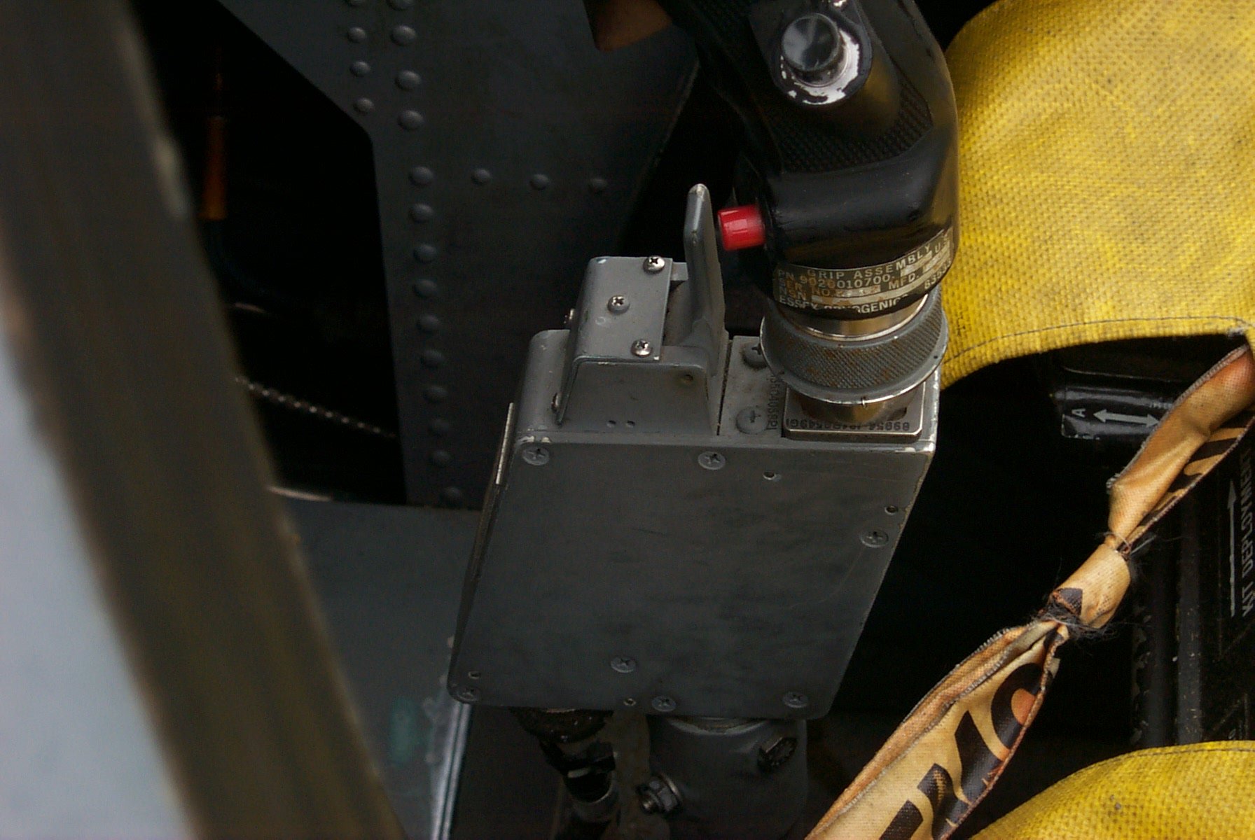
The magic for this happens in the little box that the stick grip attaches to. This box is known as a Stick Force Sensor:
This box holds a load cell beam, very similar to the one in the base that the flight grip of the F-16 plugs into. This load cell is what translates the stick force into electrical signals that the on-board computer translates into control surface movement.
The lever in front of the grip base is the Auto Pilot/Nosewheel Steering disconnect. If you’re on the ground, it disengages nose wheel steering – the red button in the picture next to the lever engages the nose wheel steering. If you’re in the air, the lever will disengage the autopilot.
Because of how important this little box is to my project, I’ve probably got more dimension data than any other part in the whole cockpit.
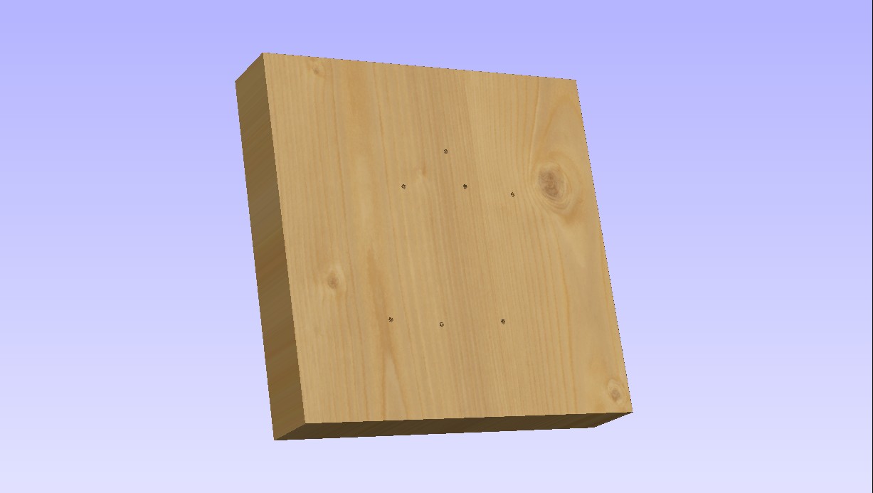
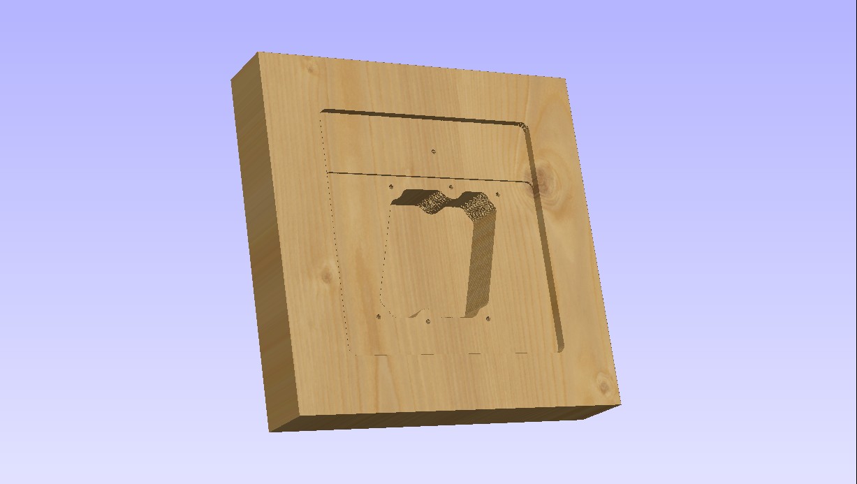
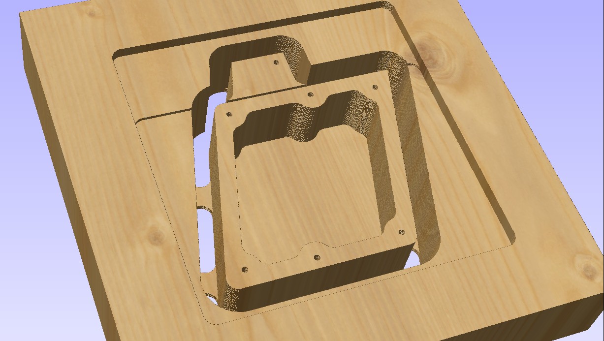
This week I’ll be making one on the ShopBot. The following images are renderings from the software that I use for creating tool paths for parts to be cut on the ShopBot. The base material is a 10″ x 10″ laminated plywood block, 2″ thick.
First up, the drill holes:
Six mounting holes and the hole for the hinge pin for the AP/NWS disconnect lever.
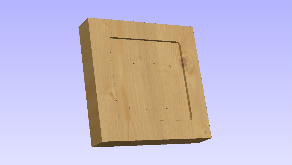
Now it gets machined down to 1.75″ thick:
Now it gets cut down a bit more to make room for the .062″ thick aluminum box cover:
This will result in a different look to the SFS box and I may change it before I cut material.
Now we create the main interior pocket for the box:
…and finally it’s time to cut the box shape out:
The tabs hold the box into the base material so it won’t shift during cutting. The box will be complete after the sides of the AP/NWS area are shaped to more closely resemble the original.
All the cutting will be done with a .50″ downshear end mill with a 1.75″ cutter length. (The tool itself is 4″ long)
IFF panel is finally completed!
It’s taken a LOT longer than I would have liked, but I was finally able to finish wiring the IFF panel today.
There are only two more panels to build completely from scratch before both cockpit side consoles are populated with the right panels. I’m going to return working on the DIY cockpit that I built (http://www.geneb.org/pitkit) in order to get it finished completely before I return to the F-15 once again.
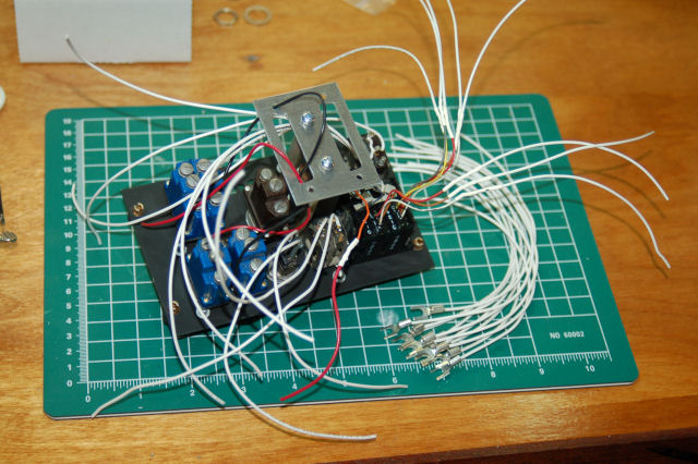
Here’s the process of wiring the IFF panel:
Pretty big rats nest, but it gets better, really. 🙂


