

Flight controls!
After many years of being disconnected, the flight controls are getting worked on!
Now that I’ve got a 3D printer, can I easily make things that would be a costly nightmare to have fabricated by someone else, or done myself in metal.
A good way to make a stick centering mechanism is to have a pushrod loaded with springs on either side of a bearing point. This is what I did with the flight controls in my 109F/X cockpit and it works great on the F-15!
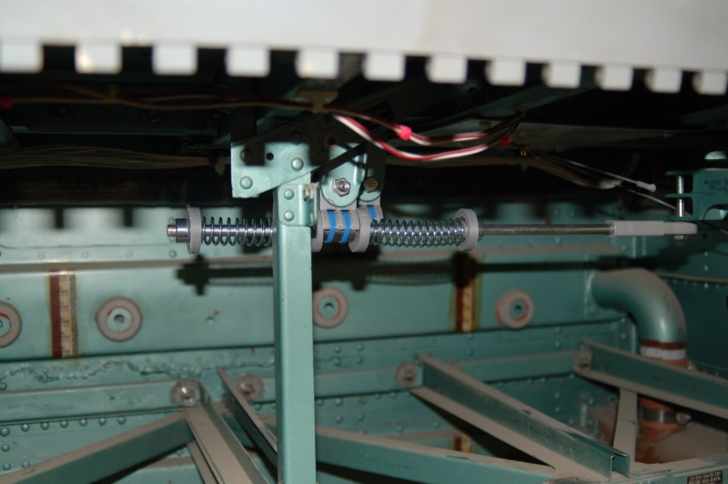
Here’s the roll axis connection:
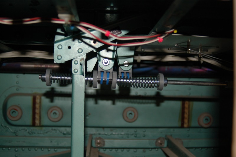
The grey parts in the image were printed on my 3D printer (a Rostock MAX by SeeMeCNC – http://www.seemecnc.com). The center point holds an LM8UU linear bearing. The bearing is held in place using a pair of wire ties. Since the bearing doesn’t receive any twisting or side-force, this is a perfectly adequate method of retaining the bearing in the mount.
The pushrod is a 5/16″ plated rod that makes it about 7.95mm in diameter – a perfect fit for the linear bearing!
The pushrod connects to the roll axis fork using a printed rod end as shown below:
The rod end is printed because I couldn’t find one that would take a 5/16″ rod, but had a 1/4″ hole in the end. The roll axis fork is drilled for a 1/4″ bolt and I didn’t want to increase the size of it.
The grey caps keep the springs centered on the shaft and prevents the springs from coming into contact with the pushrod, resulting in a nice and quiet system.
The springs I used may have to be replaced, they’re _almost_ too stiff. Once the SFS box and grip are installed, I’ll know for sure if I have to go to a lighter spring.
The pitch axis centering will be installed later – I didn’t have the parts ready when I took pics of it on Saturday (3/16/13) – I’d forgotten to print four more end caps for the spring!
The SFS box and its metal top were sanded to final shape and finish on Saturday and the SFS box got a coat of Shellac to seal it in preparation for painting. I also got the hole bored for the SFS cable connector that connects to the bottom of the box. Pics on that next week!
Updates and making new panels.
After a very long time away from the project, I’m finally getting back on track with the F-15. Rob has done an excellent job in cleaning up the canopy for installation.
The replacement trim has been rough cut and only needs final finishing and pilot holes drilled. Then it can be installed & painted!
This past Saturday, I was finally able to get the ShopBot cranked up in order to start making replacement edge-lit panels that I needed, as well as some that Steve’s Kansas F-15A needed as well.
Here’s what it looked like right off the ‘bot:

- Replacement TEWS panel
- Fire Discharge Panel (A Model)
- Jet Fuel Starter placard
- Radio ID placard
- Landing Gear handle placard
- Steer Mode placard
These were cut out of a 12×12 sheet of .236″ acrylic. The next step is to “de-panelize” them and prepare them for painting and laser engraving. Unfortunately, due to my ONGOING shop furnace issues, I still can’t paint in the shop yet.
The material the acrylic is on is “Coroplast”. It’s essentially plastic cardboard. I use an aggressive double-stick tape to hold the acrylic in place while I’m cutting it. The Coroplast is held in place by the vacuum system on the ShopBot. I can cut through the first layer of the plastic without comprimising the vacuum seal. This is the best method of cutting both acrylic and non-ferrous metals on the ShopBot. It allows for a very good material hold-down without having to use traditional mechanical clamps that could be struck by the tool on accident. It also allows for cutting very small parts that would be impractical to hold down any other way.
Right now, my Rostock MAX 3D printer is printing the first part for the new stick centering mechanism. The part holds an LM8UU linear bearing and will act as the center of the new system. I’m using Silver ABS. This particular part is for the roll axis. There are two different designs because the mounting points are a different size. The space between the bracket arms on the roll axis are 14mm, while the pitch axis spacing is 12mm. These are existing features in the underside of the cockpit that I’m using. I don’t know their original function, but they line up exactly with the pitch and roll output arms that exit through the cockpit floor.
The Screw Chase…
The trim pieces on the canopy are missing most of their screws. The screws used are a reduced head, “hi-torque” coin-slot fastener. Finding these things has been one hell of a chore.
Fortunately, the fine folks that hang out on the EAA forum were able to point me to Genuine Aircraft Hardware (http://www.gen-aircraft-hardware.com/). The folks there were not not only able to help me, they had great prices too! (Any time you hear maniacal laughter in the background, you know you’re at the right place!)
Next up is to make CAD drawings of the right side trim in order to fab a replacement for the left side that’s been damaged beyond repair…
TEWS panel pics
The TEWS panel (along with the rest) are known as a Type 5 edge-lit panel. Here’s what the “inside” of that looks like.

As you can see, there’s a series of little pockets in the panel for lamps to fit into. At the “bottom” of each of the holes is a tiny metal reflector. This helps spread the light throughout the panel and also prevents a “hot-spot” from appearing on the panel face.
Here’s what the circuit board looks like:

As you can see, it’s REALLY simple. The bulbs are very, very small. They stand about 1/8″ above the surface of the board and are a bit less than that in diameter. The metal part in the center of the board is the PCB side of the coaxial connector that provides +5V to the board. This board will draw just under 1.5A at full illumination. Incandescents are HUNGRY little beasties!
Master Caution Panel demo…
First, here’s the videos:
httpv://www.youtube.com/watch?v=mKrUuGj8YyA
httpv://www.youtube.com/watch?v=o7tJaJJbRkc
I’ve chosen to use an Arduino in conjunction with a pair of Centipede Shields to drive all the incandescent indicators in the cockpit. Just between the BIT (Built In Test) and Master Caution Panels, there’s 74 channels of output required. In order to drive those lamps, I needed to build an intermediary board that could handle both the high voltage (most of the lamps in the F-15 are 28VDC) and the high current draw. While a LED can draw as little as 15 to 20mA, the typical lamps used in the F-15 can draw up to 150mA each!
The demo shows only 16 indicators being driven. Each indicator has two lamps behind it. The lamps installed are MS25237-387 and they draw 40mA@28VDC. 16 indicators eat up 1.28A – the whole panel can consume 3.12A if everything is lit at once.
The 16 channel output board was over-designed to make sure that I could drive high-current lamps as well as handle relays and the magnetically held toggle switches that are used in a few places in the cockpit. In order to drive relays or other coil-oriented loads, “back-emf” diodes will be used in order to prevent the over-voltage created by the collapsing magnetic field in the relay or solenoid from destroying the driver circuit for that channel.
The good news is that I’ll be resuming work on the F-15 very soon – this project has been sitting on the bench awaiting final test out, which is something I _finally_ was able to accomplish while being stuck at home due to medical problems.
Work on the new collimated display designs (not for the F-15 unfortunately!) will be interwoven with new work on the F-15. After planning, plotting, designing and re-designing, for the last 11+ years, things will advance quickly once work resumes!
Accident report…
After having a discussion with a fellow simpits-tech list member, it was discovered that the Wikipedia link that discussed the loss of 80-0007 was a) lacking a citation and b) had a minor error. The page can be found here.
Since I have a copy of the “releasable” portion of the accident report, I decided to scan a few pages in order to provide the Wikipedia article a citation.
Here’s the scan:
I’ve recently obtained a new set of boards for my 16 channel power driver board – this will allow me to drive the incandescent bulbs that are in the master caution and BIT panels without having to re-lamp them with VERY spendy LED equivalents. I’ll get an update about that with more detail posted soon!
g.
A minor interlude…
Yesterday (19Dec09) I had the privilege of working with an independent filmmaker. The beginning scenes in the movie involve a couple of guys in dire straights after their F-15D suffers a catastrophic engine failure. He was lucky enough to get access to an F-15D that he could use to film the actors, but he still needed to see the correct emergency lights going off and some shots of “switch magic” where the fire supression system is activated and the relevant warnings appear on the Master Caution panel.
Here’s a picture of the Master Caution panel in “test”:

This is the first time the MCP has been illuminated while installed in the cockpit. There are 74 24v lamps in that panel and it got pretty hot for the 10 minutes or so I ran it so he could get static shots of it. HD video was also taken.
On the SFS front, I managed to ruin two blanks when they moved while being machined. 🙁 I had to lay up two new blanks and wait another 24 hours.
Until next time!
Working towards the SFS
Today I finished hunting down the missing 5 1″ oil & hydraulic instruments I couldn’t find last weekend. Of course, they showed up in the last box I could search.
Here’s the result of my search & sorting operation:

The design for the Stick Force Sensor box is completed. The SFS box is just about 1.75″ thick. Because I didn’t want to build it from acrylic or a block of aluminum, I needed to laminate four layers of 1/2″ Baltic Birch plywood together. This will give me a raw material thickness of a little more than 1.9″.

The block is 24″ long and 8″ wide. This will give me enough raw material to build two SFS boxes. One will go into the F-15 and one will go into my Me-109E/X cockpit.
I’ve got some new cutters on order and as soon as they arrive I’ll get the ShopBot to work on making the SFS boxes.
How’s THIS for a fancy light? 🙂

The AWG-20 PACS
My friend Dave is both a god of both graphics and avian photography. He’ll be writing the software that will show the various screens on the AWG-20 PACS or Programmable Armament Control Set (also known as the MPCD or Multi-Purpose Color Display)
Below is a test display he wrote for me and I’ve put my “spare” MPCD button collar frame around it so you can understand what it’s all about. 🙂

I rebuilt the MPCD that I have with a 7″ monochrome green VGA monitor. Within a couple of months of that feat (it’s not easy shoe-horning a “standard” CRT into the original enclosure!) I discovered that the MPCD is a COLOR display. Cue facepalm.
You cannot buy a 7″ color VGA display for any amount of money. I’ve tried. Repeatedly. For five years. The original display is a 5″x5″ color vector tube and while I could find a replacement, they wanted $5000.00. EACH. Cue 2nd facepalm.
I finally found a 6.4″ LCD kit from Earth LCD to the tune of $350. Painful, but no where near the pain of the original.
So what I’m doing is replacing a 1:1 aspect ratio display with a 4:3 aspect ratio display that “mostly” fits. The important part of the real estate that the LCD covers is the 20 buttons that surround the frame. With a little adjustment, it properly covers all the space that they “occupy” on the screen. I’m going to place a layer of 1/16″ or 1/8″ smoked plexiglass between the LCD and the MPCD button collar. When the unit is enclosed, no light will enter from the back and you won’t notice there’s a huge air gap above and below the LCD.
The original display had a resolution of 512×512. At 640×480, I’ll have the width I need, but I’ll be short 32 pixels (shy 16 at the top and 16 at the bottom for all practical purposes). This will make things a bit tight – there are some MPCD pages that are pretty dense, but I’m sure we’ll get it figured out.
All the bits so far…
Here’s a set of pictures that show everything that I have (minus some parts I can find!) installed in the cockpit.
The glare shields are not installed, nor is the windscreen in place..
Enjoy! 🙂


