The F-15 uses a very interesting system for the roll and pitch control – it’s both Fly by Wire and mechanical interconnect.
If you were to pin the stick in place with your knees, you can fly the jet by pressure on the grip all by itself, just like an F-16.
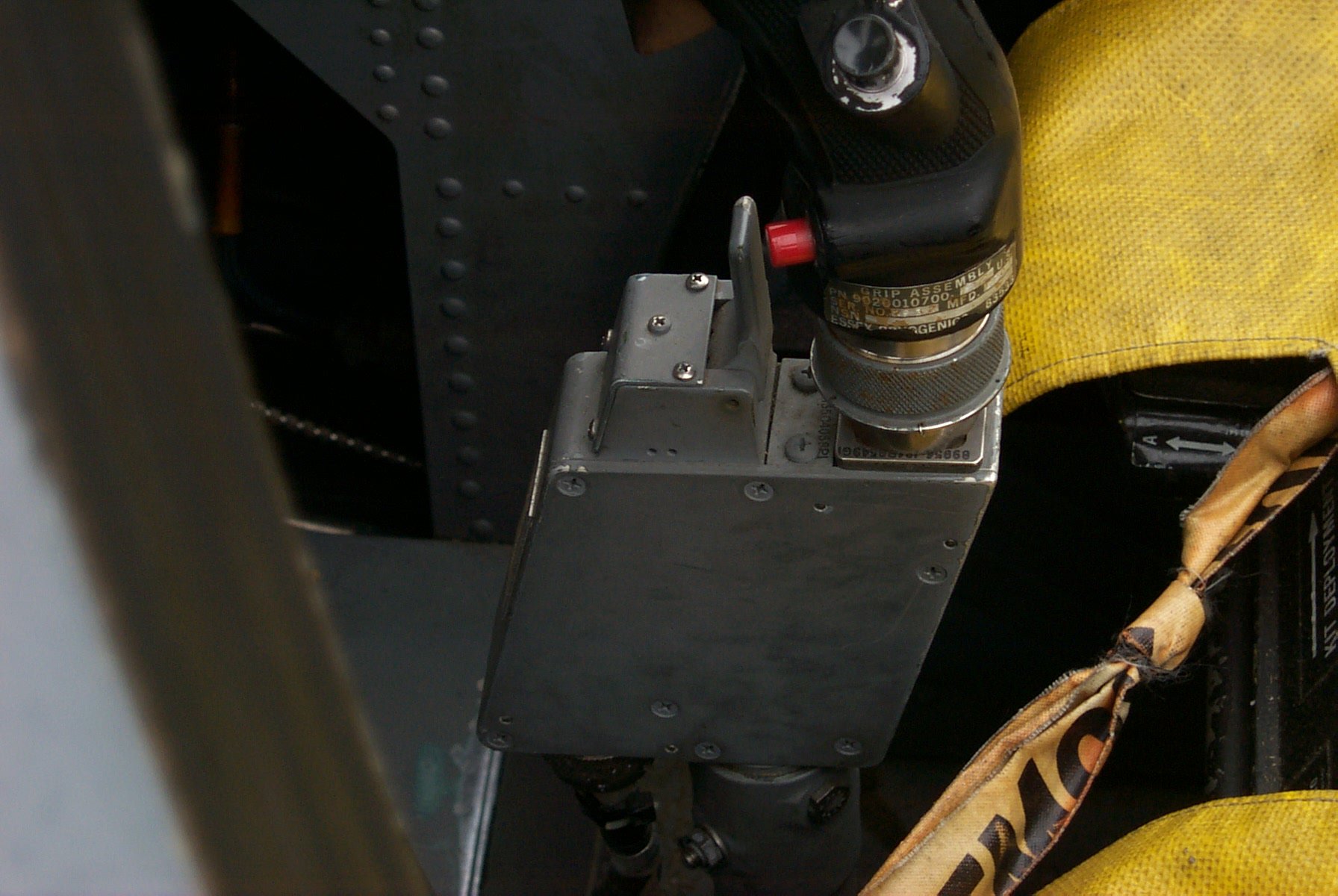
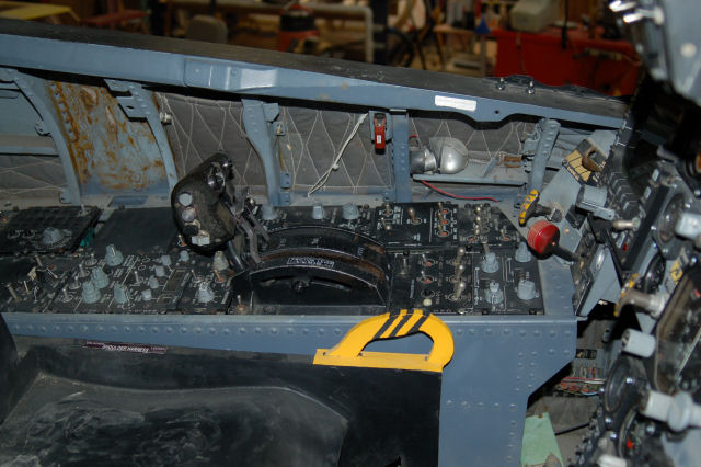
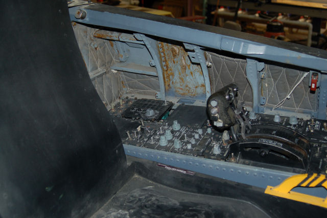
The magic for this happens in the little box that the stick grip attaches to. This box is known as a Stick Force Sensor:
This box holds a load cell beam, very similar to the one in the base that the flight grip of the F-16 plugs into. This load cell is what translates the stick force into electrical signals that the on-board computer translates into control surface movement.
The lever in front of the grip base is the Auto Pilot/Nosewheel Steering disconnect. If you’re on the ground, it disengages nose wheel steering – the red button in the picture next to the lever engages the nose wheel steering. If you’re in the air, the lever will disengage the autopilot.
Because of how important this little box is to my project, I’ve probably got more dimension data than any other part in the whole cockpit.
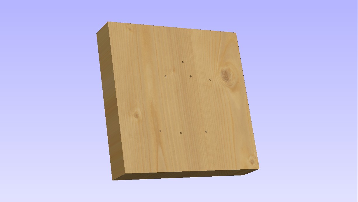
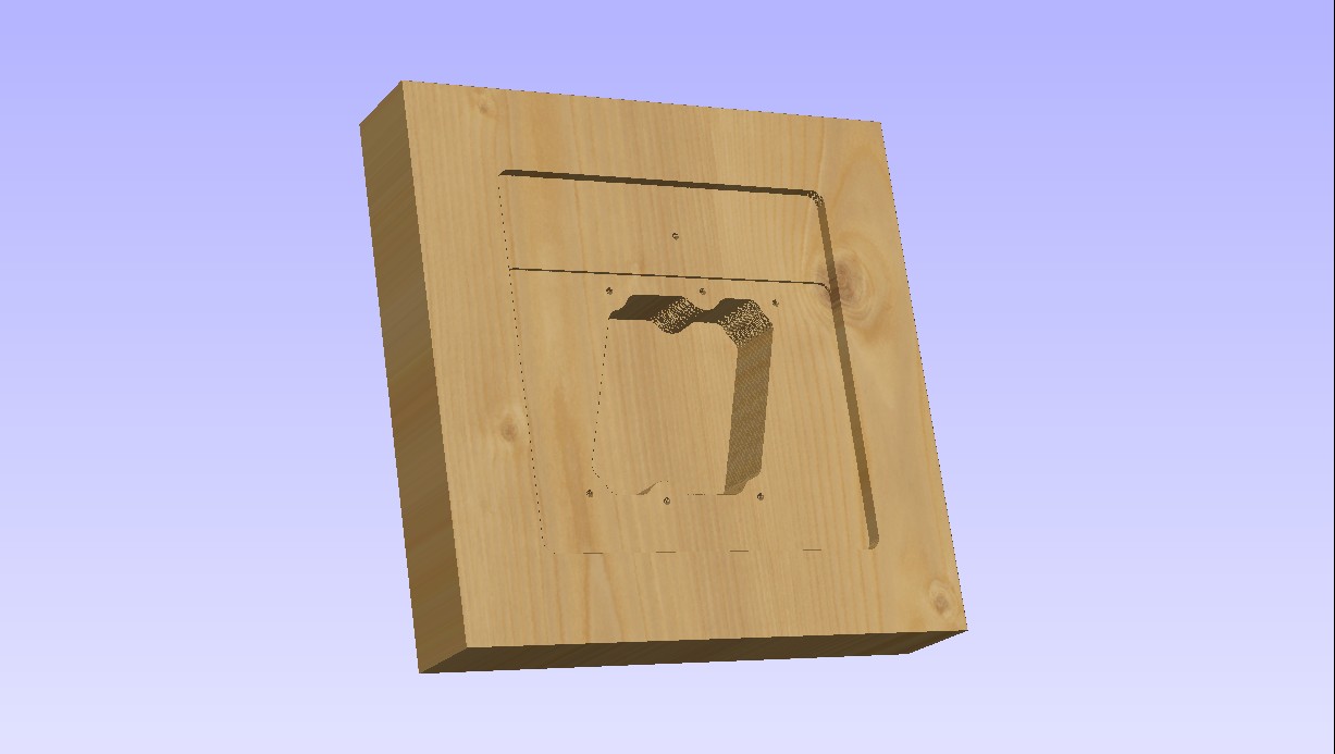
This week I’ll be making one on the ShopBot. The following images are renderings from the software that I use for creating tool paths for parts to be cut on the ShopBot. The base material is a 10″ x 10″ laminated plywood block, 2″ thick.
First up, the drill holes:
Six mounting holes and the hole for the hinge pin for the AP/NWS disconnect lever.
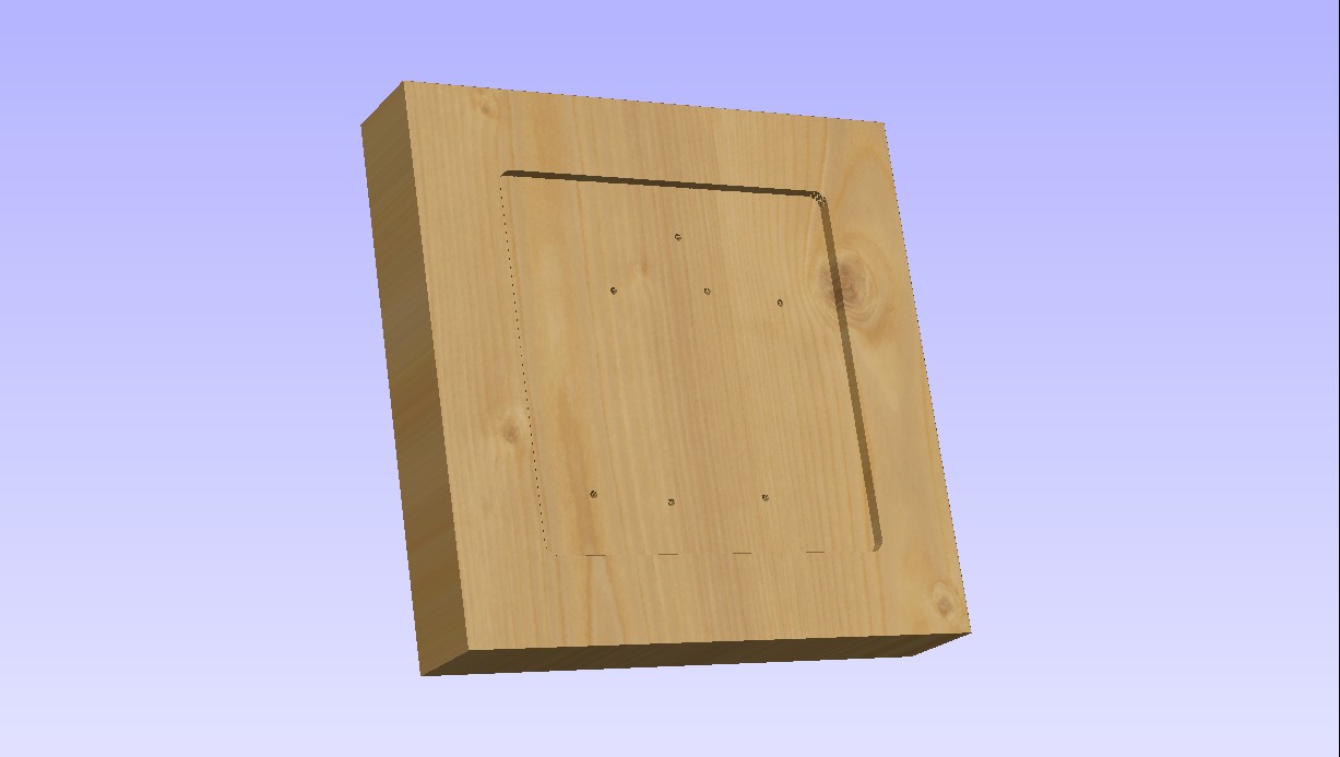
Now it gets machined down to 1.75″ thick:
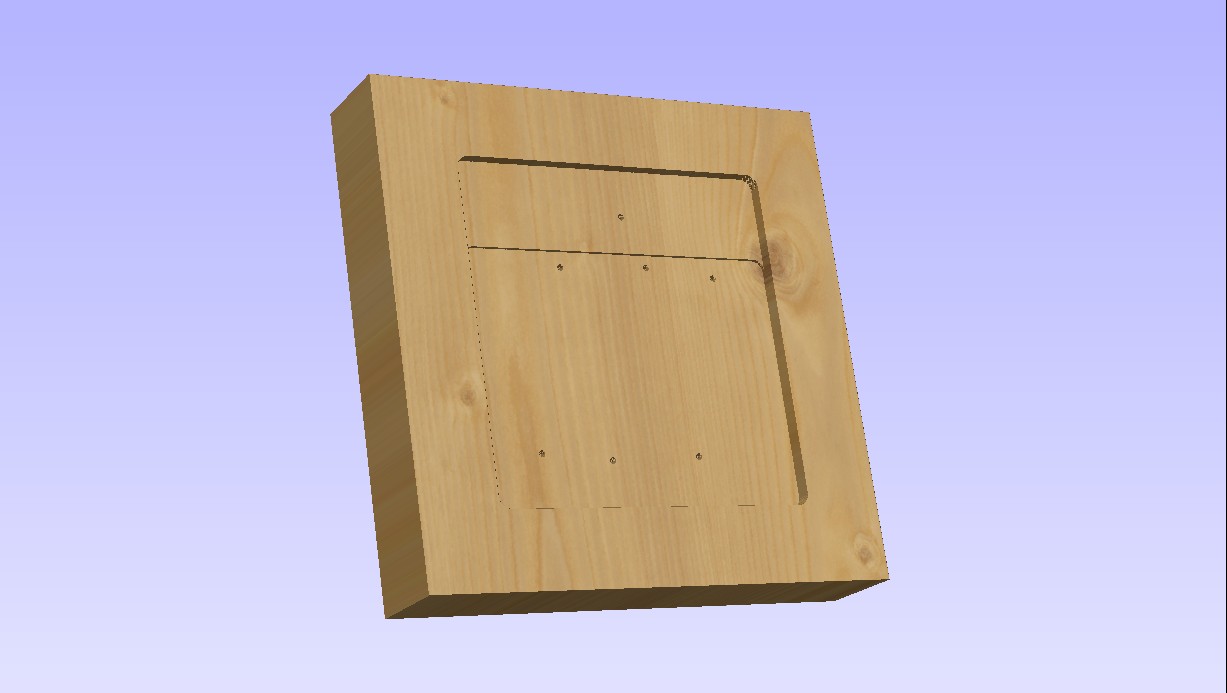
Now it gets cut down a bit more to make room for the .062″ thick aluminum box cover:
This will result in a different look to the SFS box and I may change it before I cut material.
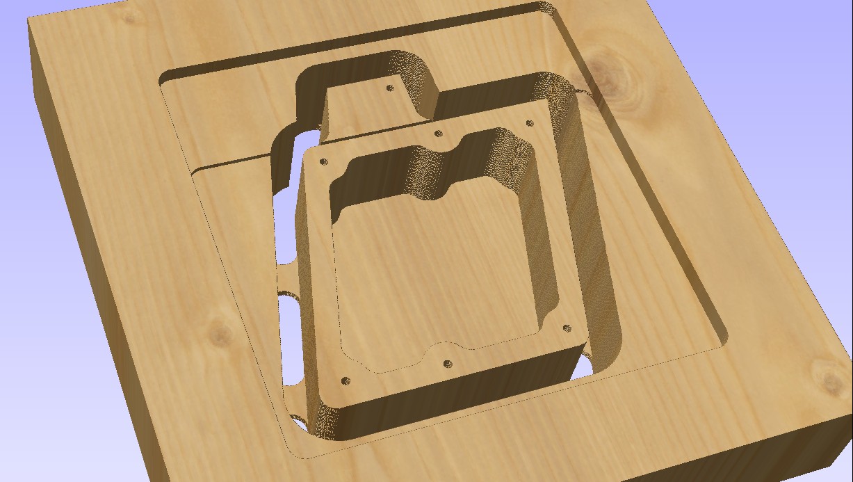
Now we create the main interior pocket for the box:
…and finally it’s time to cut the box shape out:
The tabs hold the box into the base material so it won’t shift during cutting. The box will be complete after the sides of the AP/NWS area are shaped to more closely resemble the original.
All the cutting will be done with a .50″ downshear end mill with a 1.75″ cutter length. (The tool itself is 4″ long)
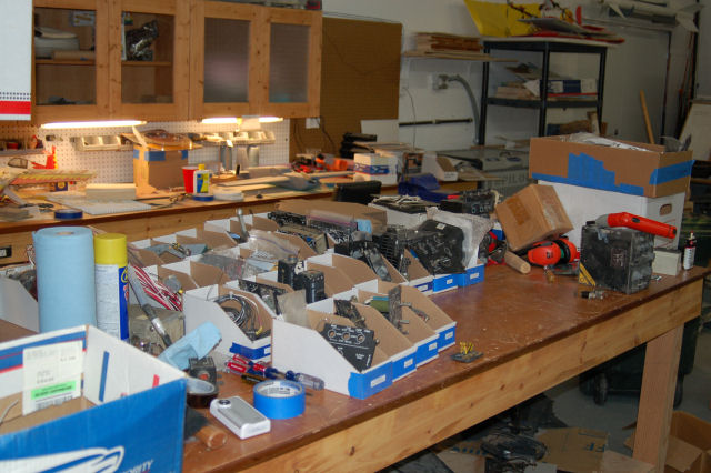
Today I finished hunting down the missing 5 1″ oil & hydraulic instruments I couldn’t find last weekend. Of course, they showed up in the last box I could search.
Here’s the result of my search & sorting operation:
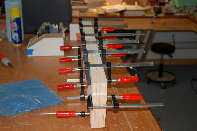
The design for the Stick Force Sensor box is completed. The SFS box is just about 1.75″ thick. Because I didn’t want to build it from acrylic or a block of aluminum, I needed to laminate four layers of 1/2″ Baltic Birch plywood together. This will give me a raw material thickness of a little more than 1.9″.
The block is 24″ long and 8″ wide. This will give me enough raw material to build two SFS boxes. One will go into the F-15 and one will go into my Me-109E/X cockpit.
I’ve got some new cutters on order and as soon as they arrive I’ll get the ShopBot to work on making the SFS boxes.
How’s THIS for a fancy light? 🙂
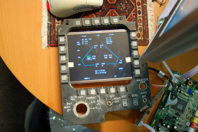
My friend Dave is both a god of both graphics and avian photography. He’ll be writing the software that will show the various screens on the AWG-20 PACS or Programmable Armament Control Set (also known as the MPCD or Multi-Purpose Color Display)
Below is a test display he wrote for me and I’ve put my “spare” MPCD button collar frame around it so you can understand what it’s all about. 🙂
I rebuilt the MPCD that I have with a 7″ monochrome green VGA monitor. Within a couple of months of that feat (it’s not easy shoe-horning a “standard” CRT into the original enclosure!) I discovered that the MPCD is a COLOR display. Cue facepalm.
You cannot buy a 7″ color VGA display for any amount of money. I’ve tried. Repeatedly. For five years. The original display is a 5″x5″ color vector tube and while I could find a replacement, they wanted $5000.00. EACH. Cue 2nd facepalm.
I finally found a 6.4″ LCD kit from Earth LCD to the tune of $350. Painful, but no where near the pain of the original.
So what I’m doing is replacing a 1:1 aspect ratio display with a 4:3 aspect ratio display that “mostly” fits. The important part of the real estate that the LCD covers is the 20 buttons that surround the frame. With a little adjustment, it properly covers all the space that they “occupy” on the screen. I’m going to place a layer of 1/16″ or 1/8″ smoked plexiglass between the LCD and the MPCD button collar. When the unit is enclosed, no light will enter from the back and you won’t notice there’s a huge air gap above and below the LCD.
The original display had a resolution of 512×512. At 640×480, I’ll have the width I need, but I’ll be short 32 pixels (shy 16 at the top and 16 at the bottom for all practical purposes). This will make things a bit tight – there are some MPCD pages that are pretty dense, but I’m sure we’ll get it figured out.
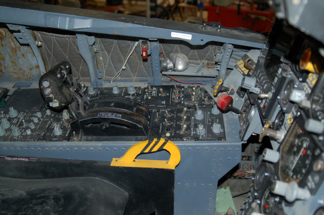
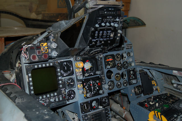
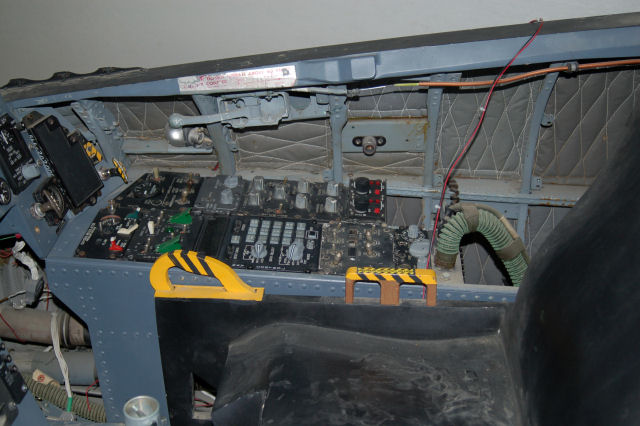
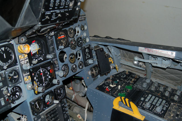
Here’s a set of pictures that show everything that I have (minus some parts I can find!) installed in the cockpit.
The glare shields are not installed, nor is the windscreen in place..
Enjoy! 🙂
It’s taken a LOT longer than I would have liked, but I was finally able to finish wiring the IFF panel today.
There are only two more panels to build completely from scratch before both cockpit side consoles are populated with the right panels. I’m going to return working on the DIY cockpit that I built (http://www.geneb.org/pitkit) in order to get it finished completely before I return to the F-15 once again.
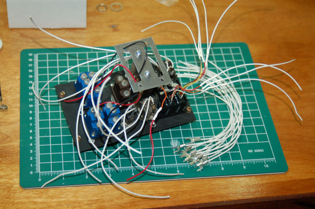
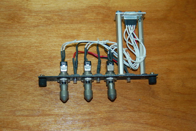
Here’s the process of wiring the IFF panel:
Pretty big rats nest, but it gets better, really. 🙂
After a number of delays, I finally got the EW panel completed!
Here’s what the panel assembly looks like:
You’ll notice that I’ve abandoned the tiny nylon wire ties in favor of waxed lacing cord. It looks a _lot_ nicer and much more “authentic”. Waxed lacing cord is used on “real” panels in both commercial simulators and flying aircraft.
This past week has seen some great progress on the panel front.
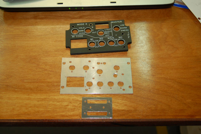
First up is the nearly completed IFF panel. After breaking a few tools due to feeding too fast, I was finally able to get the parts for the IFF mounting plate cut:
Through some further experimenting, the design of the REPLY indicator was changed a little bit. It now uses two .125″ diffuser layers and a single .062″ Rowmark lettering layer. This results in a MUCH better visual result, with no hot spots or faded areas in the indicator.
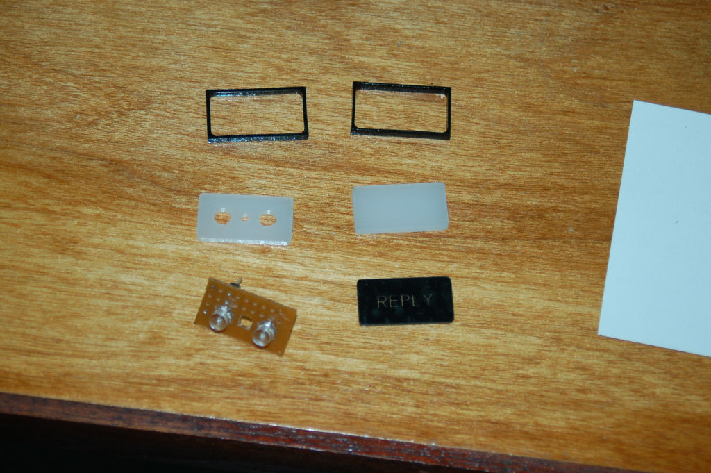
The parts that make up the REPLY indicator
Only the back diffusion layer has holes cut out for the LEDs. The LEDs themselves are shaped like flat top cylinders instead of the rounded top you normally see with LEDs. The two small black frames were made to more closely emulate the look of the original indicator.
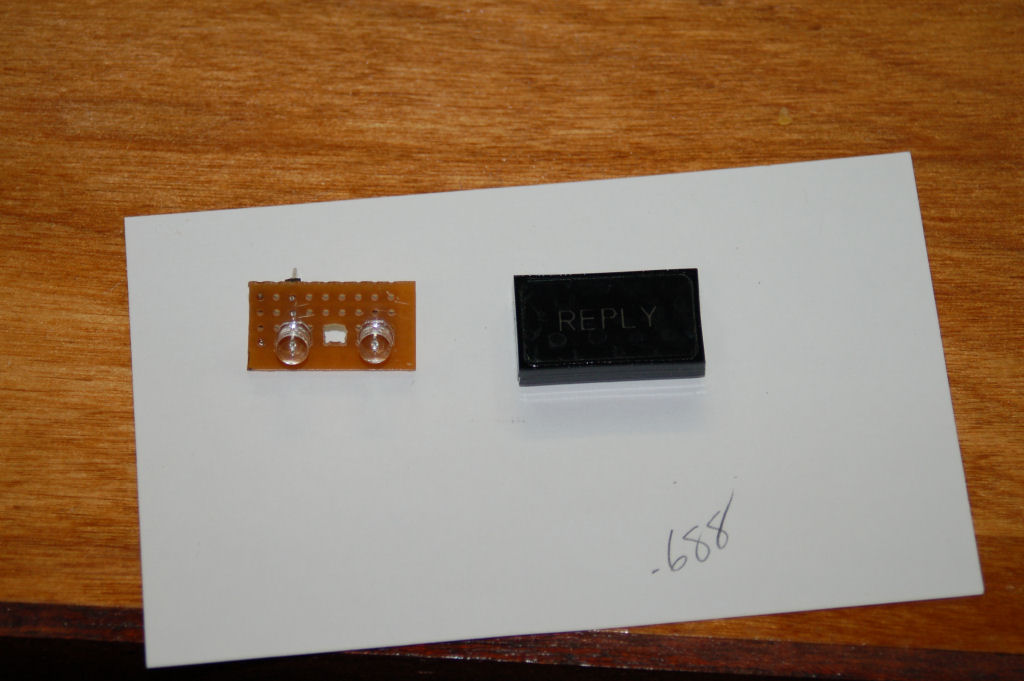
The assembled REPLY indicator next to the LED circuit board.
The two LEDs used are 3.0v 180 degree FOV green LEDs. These LEDs can be purchased from here: http://myworld.ebay.com/cece718.
Here’s a short video that shows the indicator in action. Note that the camera I use was pretty much overwhelmed by the light from the LEDs. It’s really not that bright in person.
httpv://www.youtube.com/watch?v=BK9-v67XUFw
Some 2 years ago, I finished the main construction for the new FUEL panel in the simulator. Other things came up and I never got back to finishing the panel. As of today, it’s finally finished.
The wiring needed to be done and I didn’t want to mickey mouse the process. I created a little 25 hole template that would allow me to cut the wiring to the right length for mounting into the DB25 connector I’d chosen for this panel.
httpv://www.youtube.com/watch?v=2-pumNCcbEU
The new panel that I’m working on is for the IFF control panel in the F-15. Since I have a “real” edge-lit panel for this, I only need to make the metal mounting plate and the “REPLY” indicator that it needs.
Here’s what the panel itself looks like:
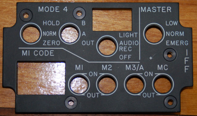
IFF Control Panel


