

| Parameter Name | Source | Range | Resolution | Samples Per Second |
| Left Aileron Position | Transducer | +/- 20 deg | 0.05 deg | 53.33 |
| Right Aileron Position | Transducer | +/- 20 deg | 0.05 deg | 53.33 |
| Left Stabilator Position | Bus – 16 bit | -30deg to +15 deg | 0.006 deg | 26.66 |
| Right Stabilator Position | Bus – 16 bit | -30deg to +15 deg | 0.006 deg | 26.66 |
| Left Rudder Position | Transducer | +/- 3 0deg | 0.04 deg | 53.33 |
| Right Rudder Position | Transducer | +/- 30 deg | 0.04deg | 53.33 |
| Speed Brake Position | Transducer | 0 to 45 deg | 0.03 deg | 53.33 |
| Longitudinal Stick Force | Transducer | +/- 25lbs | 0.04lbs | 53.33 |
| Lateral Stick Force | Transducer | +/- 20lbs | 0.05lbs | 53.33 |
| Longitudinal Stick Position | Transducer | -3 to 6in | 0.008in | 53.33 |
| Lateral Stick Position | Transducer | +/- 4in | 0.007in | 53.33 |
| Right Rudder Pedal Force | Transducer | +/- 200lbs | 0.3lbs | 53.33 |
| Left Rudder Pedal Force | Transducer | +/- 200lbs | 0.3lbs | 53.33 |
| Right Rudder Pedal Position | Transducer | +/- 4in | 0.02in | 53.33 |
| Left Rudder Pedal Position | Transducer | +/- 4in | 0.02in | 53.33 |
| Right Power Lever Angle | Transducer | 0deg to 130deg | 0.09deg | 6.66 |
| Left Power Lever Angle | Transducer | 0deg to 130deg | 0.09deg | 6.66 |
| Left Fuel Flow | Transducer | 0 to 100,000 lbs/hr | 0.024 lbs/hr | 6.66 |
| Right Fuel Flow | Transducer | 0 to 100,000 lbs/hr | 0.024 lbs/hr | 6.66 |
| Left Fuel Flow | Transducer | 0 to 100,000 lbs/hr | 0.024 lbs/hr | 6.66 |
| Left Engine Nozzle Area | Transducer | 2.5 to 65 sqft | 0.022 sqft | 6.66 |
| Right Engine Nozzle Area | Transducer | 2.5 to 65 sqft | 0.022 sqft | 6.66 |
| Left Core Speed (N2) | Production System | 0 to 110% | 0.2% | 53.33 |
| Right Core Speed (N2) | Production System | 0 to 110% | 0.2% | 53.33 |
| Pressure Altitude | Bus – 16 bit | -1,560 to 80,337ft | 1.25ft | 26.66 |
The flight control system on the F-15 is a cross between a fly-by-wire system and a standard hydro-mechanical system. The F-15 has a system called the CAS, or Control Augmentation System that combines the best features of the old and new styles of flight controls.
In order to accomplish this, McDonnell-Douglas needed a way to detect the amount and direction of force the pilot was applying to the flight grip. This is how the SFS or Stick Force Sensor box was born. This box not only joins the grip to the stick base, but also contains a “load beam”. This is a special electronic device that tells the flight control computer how much force the pilot is applying to the stick and in what direction. The SFS box also contains the Autopilot Disconnect and Nosewheel Steering paddle.
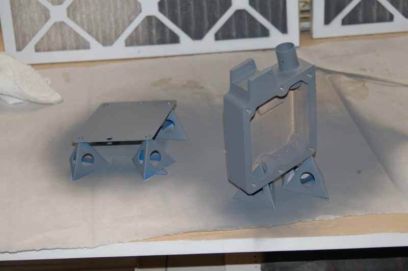
Here’s what the components of my implementation look like:
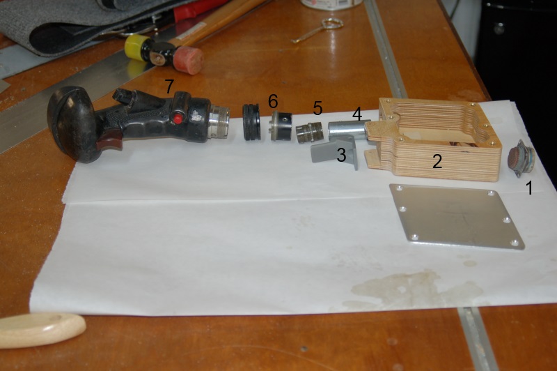
SFS Box Parts
- 57 pin cannon socket
- CNC machined Baltic Birch SFS box and aluminum cover
- AP/NWS paddle (3D printed)
- Replica Load Beam
- 57 pin cannon socket
- Grip support and threaded locking ring
- F-15C, Post-MSIP II Flight Grip (made of pure unobtanium!)
Part #1 – the 57 pin cannon plug was part of the original wiring harness for the SFS box. However, instead of being mounted to the box, this connector was attached to the cockpit floor with four screws. The other end of the cable (not shown) was a 57 pin cannon plug that mated to the SFS box itself. I’m going to rebuild the harness using a different connector to pass the wiring through the cockpit floor and use the original parts to build a visually correct SFS box.
Part #2 – the machined SFS box was covered here a number of years ago. Other projects and an ugly case of Stage IIIB lung cancer put the whole thing on hold for a long time.
Part #3 is a pretty good replica of the original AP/NWS paddle. I printed it on my Rostock MAX 3D printer.
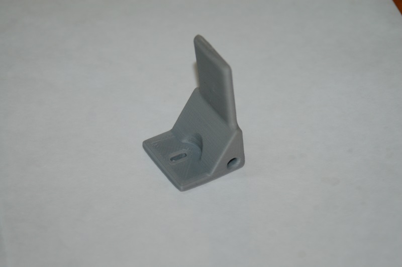
AP/NWS Paddle
The part is 30mm tall and 30mm wide at the base. It’s not an exact copy of the paddle, but it’s pretty close!
Part #4 – the “load beam” is simply a short piece of 3/4″ EMT that’s been turned on a lathe to increase the inside diameter a bit in order that the 57 pin cannon plug (Part 5) can fit inside.
Part #5 – the 57 pin cannon plug mates to the keyed socket on the flight grip.
Part #6 – the lower ring is custom fabricated by a friend of mine and the threaded ring was a donor part from another aircraft. Fortunately the USAF loves their standards, so most of the parts at that level are the same with respect to thread diameter and pitch.
I’ve got the pinout for the grip and I just need to verify it with a meter. Once I’m confident that I have a 100% good pinout and all the switches work, I’ll build the harness that joins the two cannon connectors together and then permanently mount the connector to the bottom of the SFS box.
Not shown is a Delrin post that bolts to the bottom of the SFS box – this is what mates the SFS box to the lower stick mechanism in the cockpit.
This past week I got the “beam” glued into the SFS box using JB Weld:
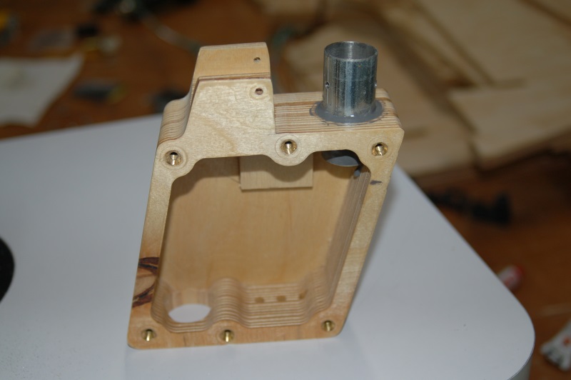
“Beam” mounted to the SFS box.
I’m going to add a smaller support piece in there to help protect the tube against aggressive back-force. It’s well supported to the rear, but not to the front.
The little square of material you can see is where the micro-switch for the AP/NWS paddle goes.
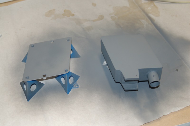
SFS painted with a first coat of primer.
Another angle…
I used a Krylon flat primer and before I install it into the cockpit, I’ll shoot it again with the correct FS color that it should be. The grey primer isn’t light enough.
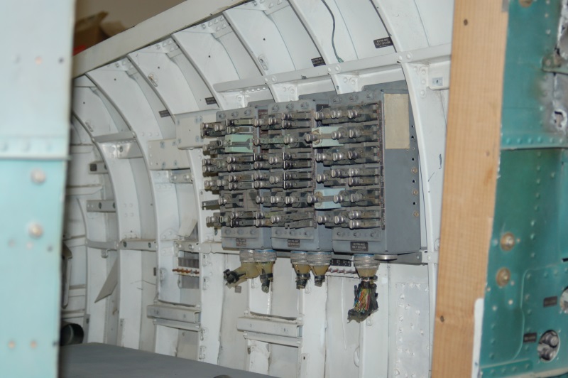
A number of years ago, I scored a pile of the Bay 5 relay boxes on eBay. I got tired of moving them around the shop this week, so I installed them. 🙂 Each one is in the correct location according to the matching placards on each one. 🙂
More next week!
After many years of being disconnected, the flight controls are getting worked on!
Now that I’ve got a 3D printer, can I easily make things that would be a costly nightmare to have fabricated by someone else, or done myself in metal.
A good way to make a stick centering mechanism is to have a pushrod loaded with springs on either side of a bearing point. This is what I did with the flight controls in my 109F/X cockpit and it works great on the F-15!
Here’s the roll axis connection:
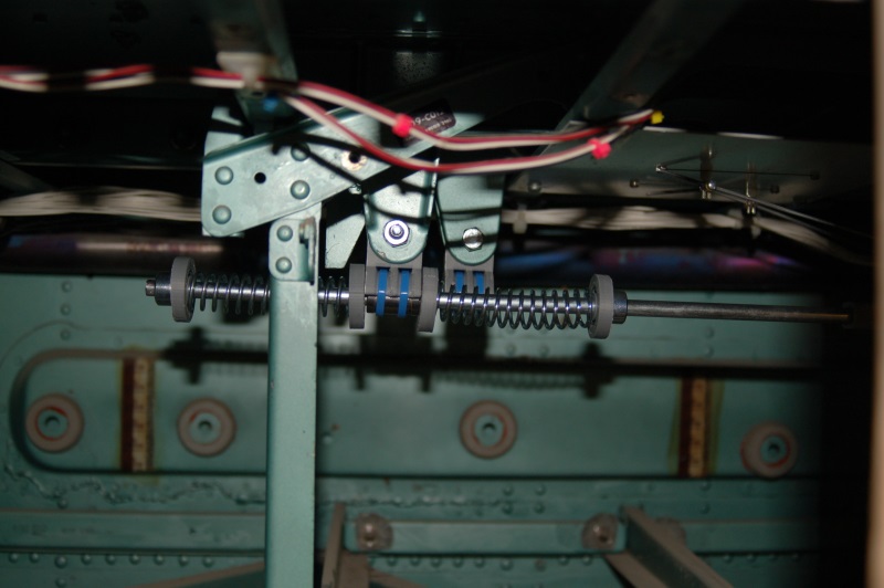
The grey parts in the image were printed on my 3D printer (a Rostock MAX by SeeMeCNC – http://www.seemecnc.com). The center point holds an LM8UU linear bearing. The bearing is held in place using a pair of wire ties. Since the bearing doesn’t receive any twisting or side-force, this is a perfectly adequate method of retaining the bearing in the mount.
The pushrod is a 5/16″ plated rod that makes it about 7.95mm in diameter – a perfect fit for the linear bearing!
The pushrod connects to the roll axis fork using a printed rod end as shown below:
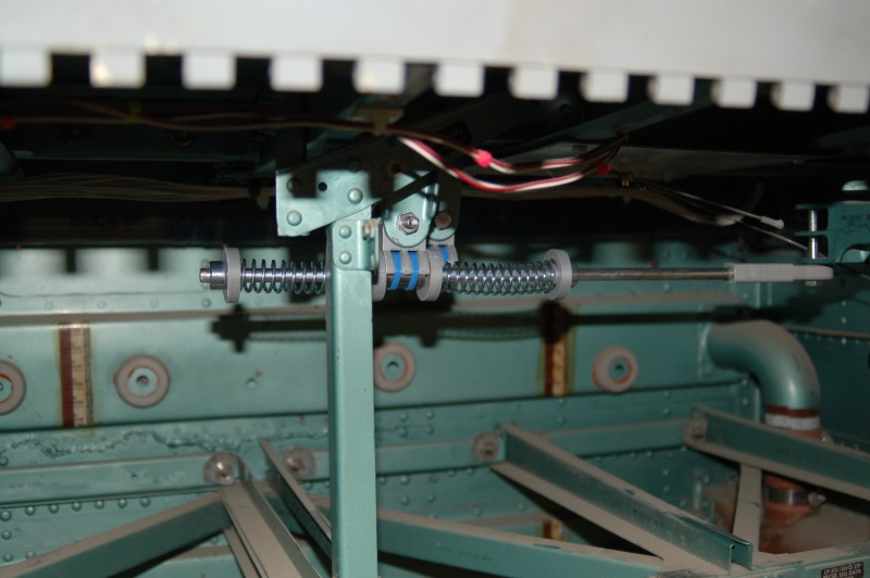
The rod end is printed because I couldn’t find one that would take a 5/16″ rod, but had a 1/4″ hole in the end. The roll axis fork is drilled for a 1/4″ bolt and I didn’t want to increase the size of it.
The grey caps keep the springs centered on the shaft and prevents the springs from coming into contact with the pushrod, resulting in a nice and quiet system.
The springs I used may have to be replaced, they’re _almost_ too stiff. Once the SFS box and grip are installed, I’ll know for sure if I have to go to a lighter spring.
The pitch axis centering will be installed later – I didn’t have the parts ready when I took pics of it on Saturday (3/16/13) – I’d forgotten to print four more end caps for the spring!
The SFS box and its metal top were sanded to final shape and finish on Saturday and the SFS box got a coat of Shellac to seal it in preparation for painting. I also got the hole bored for the SFS cable connector that connects to the bottom of the box. Pics on that next week!
After a very long time away from the project, I’m finally getting back on track with the F-15. Rob has done an excellent job in cleaning up the canopy for installation.
The replacement trim has been rough cut and only needs final finishing and pilot holes drilled. Then it can be installed & painted!
This past Saturday, I was finally able to get the ShopBot cranked up in order to start making replacement edge-lit panels that I needed, as well as some that Steve’s Kansas F-15A needed as well.
Here’s what it looked like right off the ‘bot:

- Replacement TEWS panel
- Fire Discharge Panel (A Model)
- Jet Fuel Starter placard
- Radio ID placard
- Landing Gear handle placard
- Steer Mode placard
These were cut out of a 12×12 sheet of .236″ acrylic. The next step is to “de-panelize” them and prepare them for painting and laser engraving. Unfortunately, due to my ONGOING shop furnace issues, I still can’t paint in the shop yet.
The material the acrylic is on is “Coroplast”. It’s essentially plastic cardboard. I use an aggressive double-stick tape to hold the acrylic in place while I’m cutting it. The Coroplast is held in place by the vacuum system on the ShopBot. I can cut through the first layer of the plastic without comprimising the vacuum seal. This is the best method of cutting both acrylic and non-ferrous metals on the ShopBot. It allows for a very good material hold-down without having to use traditional mechanical clamps that could be struck by the tool on accident. It also allows for cutting very small parts that would be impractical to hold down any other way.
Right now, my Rostock MAX 3D printer is printing the first part for the new stick centering mechanism. The part holds an LM8UU linear bearing and will act as the center of the new system. I’m using Silver ABS. This particular part is for the roll axis. There are two different designs because the mounting points are a different size. The space between the bracket arms on the roll axis are 14mm, while the pitch axis spacing is 12mm. These are existing features in the underside of the cockpit that I’m using. I don’t know their original function, but they line up exactly with the pitch and roll output arms that exit through the cockpit floor.
The trim pieces on the canopy are missing most of their screws. The screws used are a reduced head, “hi-torque” coin-slot fastener. Finding these things has been one hell of a chore.
Fortunately, the fine folks that hang out on the EAA forum were able to point me to Genuine Aircraft Hardware (http://www.gen-aircraft-hardware.com/). The folks there were not not only able to help me, they had great prices too! (Any time you hear maniacal laughter in the background, you know you’re at the right place!)
Next up is to make CAD drawings of the right side trim in order to fab a replacement for the left side that’s been damaged beyond repair…
St. Roger, the patron saint of wayward aircraft bits delivered unto me a windscreen and canopy last night!

As you can see, it’s pretty rough. We figure it was either ejected or purposely damaged for whatever reason. It CAN be salvaged however.
Finding a replacement glass section (lexan actually) is essentially impossible. That is ok however, because since I don’t have the part of the fuselage where the hinge mounted, I really can’t make it an articulating canopy anyway.
What I’ll do is remove the broken lexan parts and then mount the canopy in the closed & locked position to the F-15. Without the forward canopy glass there, you can just step over the rail to get into the cockpit.
The canopy is also bent a bit in the middle, but I’m sure I can straighten it out well enough to get it installed. I’ll have to fabricate a replacement trim strip as the one on the left is broken where the canopy is bent.

The good news is that the mounts for the compass and lock/shoot lights are still in place. The side handles are present as well. I can’t wait to get this thing fixed and installed! It’s gonna look kind of odd without the forward glass, but who cares!
Here’s a shot of the new windscreen:

The windscreen has a few gouges in it, but it’s actually in a lot better shape than the A model windscreen that came with the cockpit when I originally got it. I’m going to test some Novus polish I have to see how well it works fixing some of the lighter scratches. I think Novus also makes a fill that will handle the deeper gouges.
[Update: 20Nov12]
Thanks to Matt who sent me a link to a Craigslist ad for an F-15 canopy, it looks like I may get it. I’m working on making arrangements with the seller right now. How’s that for cool? 🙂
I also got the images resized thanks to a new plugin I found for WordPress called ImagePro.
The TEWS panel (along with the rest) are known as a Type 5 edge-lit panel. Here’s what the “inside” of that looks like.

As you can see, there’s a series of little pockets in the panel for lamps to fit into. At the “bottom” of each of the holes is a tiny metal reflector. This helps spread the light throughout the panel and also prevents a “hot-spot” from appearing on the panel face.
Here’s what the circuit board looks like:

As you can see, it’s REALLY simple. The bulbs are very, very small. They stand about 1/8″ above the surface of the board and are a bit less than that in diameter. The metal part in the center of the board is the PCB side of the coaxial connector that provides +5V to the board. This board will draw just under 1.5A at full illumination. Incandescents are HUNGRY little beasties!

A couple of years ago I scored a nearly complete TEWS control panel from a gent in Cypress. The panel was scuffed pretty badly and some nimrod tore out two of the three FAIL indicators. However, there’s enough left for me to work with. 🙂
As you can see above, the panel itself isn’t in such bad shape except the FAIL indicators.
Last Saturday I started the artwork on the replacement edge lit panel for the TEWS control:

I go through an iterative process that involves measuring the original and transferring those dimensions to an AutoCAD drawing. Periodically I’ll throw an 8.5×11 sheet of printer paper into the laser and cut a test to see how it matches to the original. At the stage this picture was taken, the panel art is complete. The next step will be to duplicate the pocketing on the back of the panel in order to reuse the original circuit board that carries all the grain-of-rice lamps that light up the panel.
After the edge-lit panel is complete, I still need to find two replacement FAIL indicators, otherwise I’ll need to fab three new ones in a similar fashion to what I did for the REPLY indicator on the IFF panel.
First, here’s the videos:
httpv://www.youtube.com/watch?v=mKrUuGj8YyA
httpv://www.youtube.com/watch?v=o7tJaJJbRkc
I’ve chosen to use an Arduino in conjunction with a pair of Centipede Shields to drive all the incandescent indicators in the cockpit. Just between the BIT (Built In Test) and Master Caution Panels, there’s 74 channels of output required. In order to drive those lamps, I needed to build an intermediary board that could handle both the high voltage (most of the lamps in the F-15 are 28VDC) and the high current draw. While a LED can draw as little as 15 to 20mA, the typical lamps used in the F-15 can draw up to 150mA each!
The demo shows only 16 indicators being driven. Each indicator has two lamps behind it. The lamps installed are MS25237-387 and they draw 40mA@28VDC. 16 indicators eat up 1.28A – the whole panel can consume 3.12A if everything is lit at once.
The 16 channel output board was over-designed to make sure that I could drive high-current lamps as well as handle relays and the magnetically held toggle switches that are used in a few places in the cockpit. In order to drive relays or other coil-oriented loads, “back-emf” diodes will be used in order to prevent the over-voltage created by the collapsing magnetic field in the relay or solenoid from destroying the driver circuit for that channel.
The good news is that I’ll be resuming work on the F-15 very soon – this project has been sitting on the bench awaiting final test out, which is something I _finally_ was able to accomplish while being stuck at home due to medical problems.
Work on the new collimated display designs (not for the F-15 unfortunately!) will be interwoven with new work on the F-15. After planning, plotting, designing and re-designing, for the last 11+ years, things will advance quickly once work resumes!
After having a discussion with a fellow simpits-tech list member, it was discovered that the Wikipedia link that discussed the loss of 80-0007 was a) lacking a citation and b) had a minor error. The page can be found here.
Since I have a copy of the “releasable” portion of the accident report, I decided to scan a few pages in order to provide the Wikipedia article a citation.
Here’s the scan:
I’ve recently obtained a new set of boards for my 16 channel power driver board – this will allow me to drive the incandescent bulbs that are in the master caution and BIT panels without having to re-lamp them with VERY spendy LED equivalents. I’ll get an update about that with more detail posted soon!
g.

